
01
Part and bend line
Provide total part length, bend-line position, geometry, handling envelope and the reference used across the machine junction.
Tandem Press Brake | 2-WAD
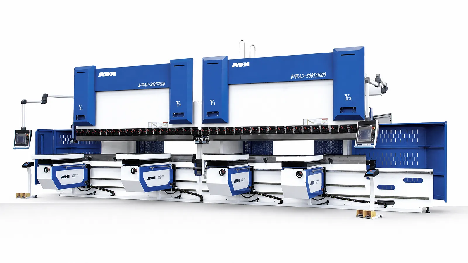
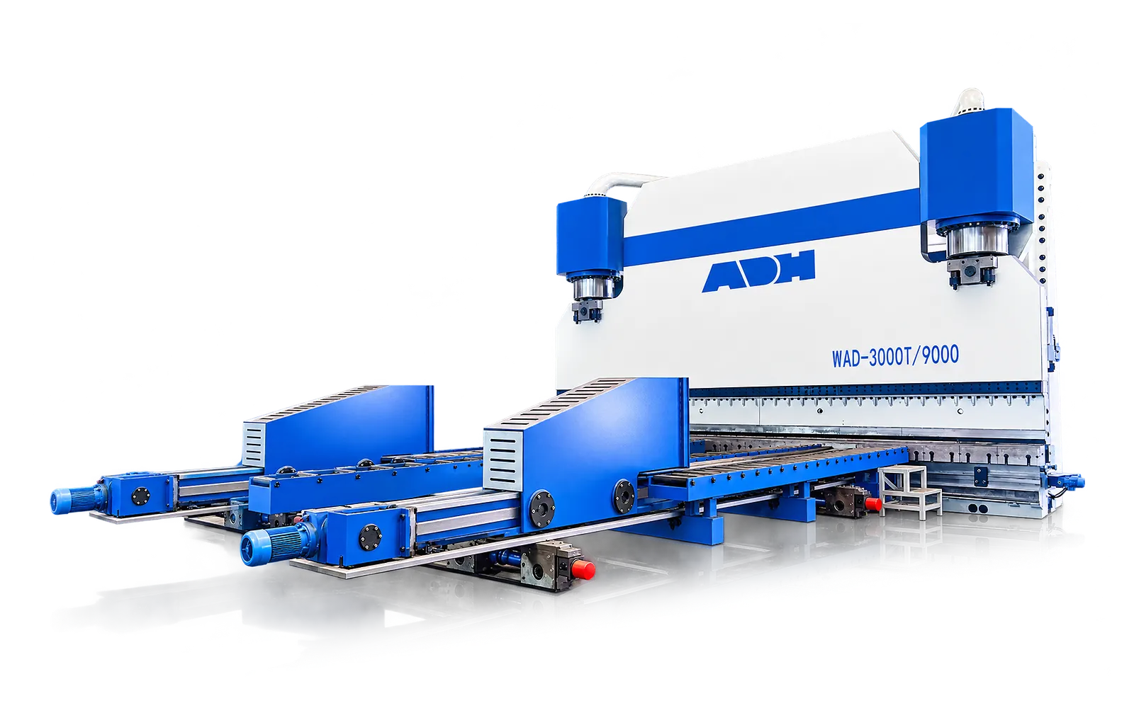
The 2-WAD tandem arrangement pairs two electro-hydraulic press brakes for long workpieces. Define the tooling alignment, force distribution and controls for independent operation and for one synchronized bend across both machines.
Technical specifications
The 2 × WAD-300T/4000 configuration pairs two 300-tonne presses. Each station can bend its own workpiece or the pair can run a synchronized bend. For a part crossing the machine junction, confirm usable length, load distribution and tooling alignment on the joint layout.
| Specification | Configuration |
|---|---|
| Press arrangement | Two WAD-300T/4000 stations |
| Nominal bending force per station | 3,000 kN (300 tonnes) |
| Bending length per station | 4,000 mm |
| Operating modes | Independent presses or synchronized tandem operation |
| Ram synchronization | ±0.02 mm synchronization accuracy in linked operation |
| Feedback and compensation | Independent linear scales and automatic deflection compensation |
| Long-part application | Confirm usable length across the joint, tooling alignment and permitted load distribution for the actual part. |
Application fit
Define length, force distribution, tooling, alignment, handling, foundation and safe operating modes.
01
Provide total part length, bend-line position, geometry, handling envelope and the reference used across the machine junction.
02
Record material strength, thickness, force per metre, V-opening, load distribution and allowable tooling line load.
03
Define worktable height, tooling centreline, opening, throat, backgauges, crowning and the required tandem or independent modes.
04
Confirm foundation, lifting, long-part support, operator positions, guarded zones, emergency-stop logic and acceptance tests.
Machine in operation
Watch a tandem bending demonstration. Capacity, configuration and acceptance checks are specific to the paired machines and application.
Watch on YouTube (opens in a new tab)Product systems
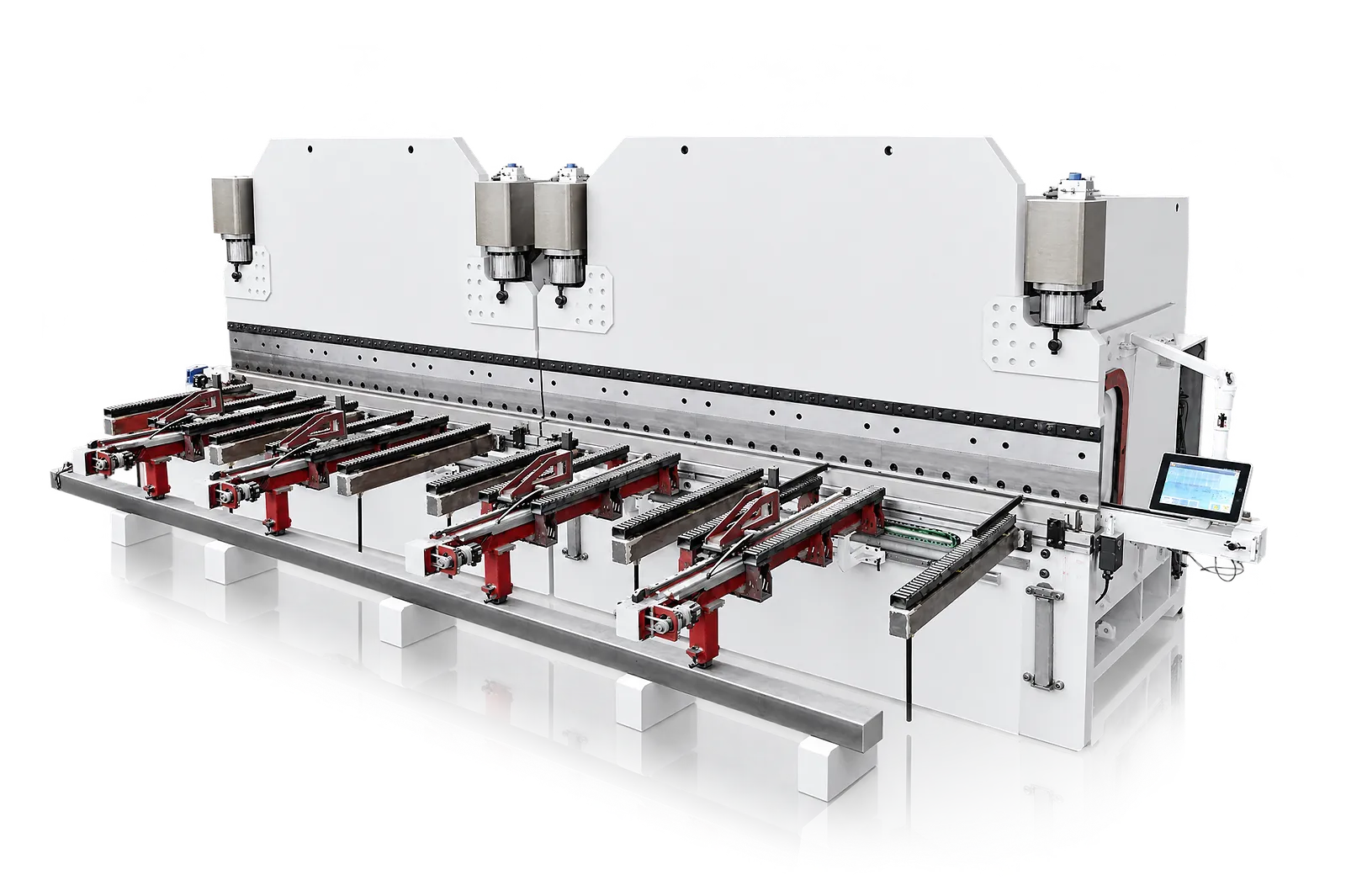
A tandem installation coordinates two machines around one long workpiece. Alignment, linked control, compensation and handling must be planned as a complete bending line.
01
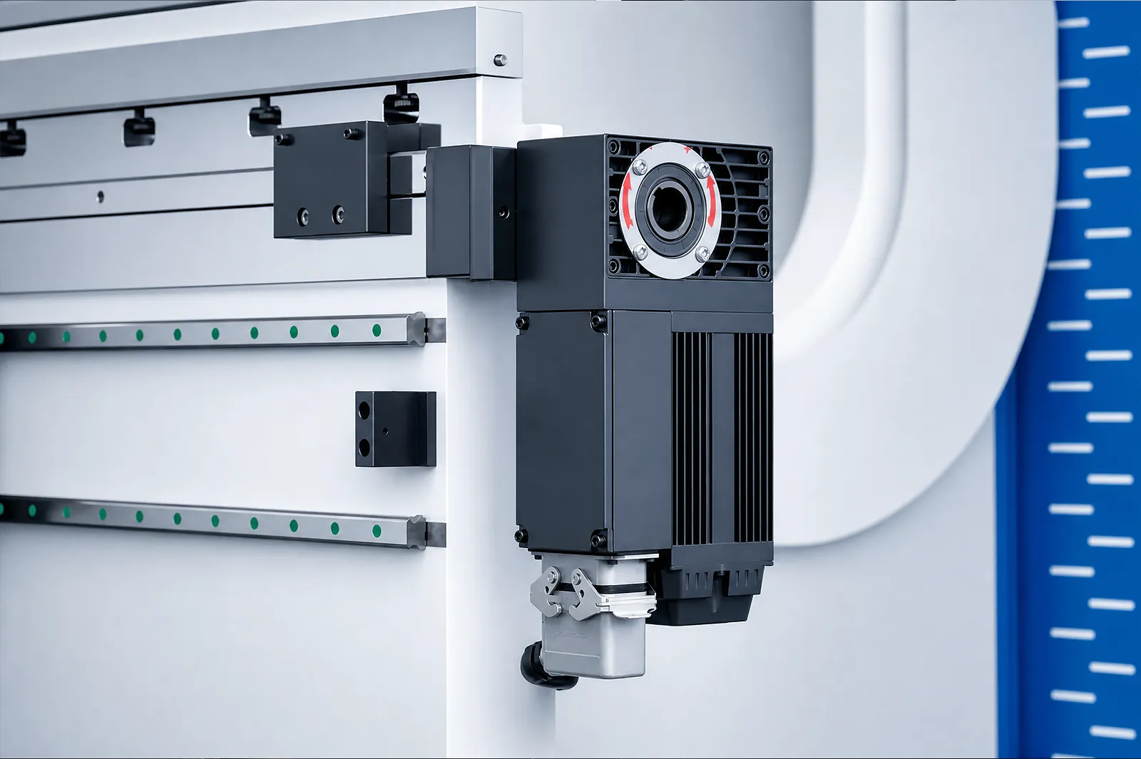
The two machines are aligned around a common tooling and workpiece reference. Frame geometry, worktable alignment, foundation and the junction between machines are commissioned together.
Select the usable working envelope and load distribution for the long part. Standalone machine data alone does not define a tandem specification.
Linked ram control
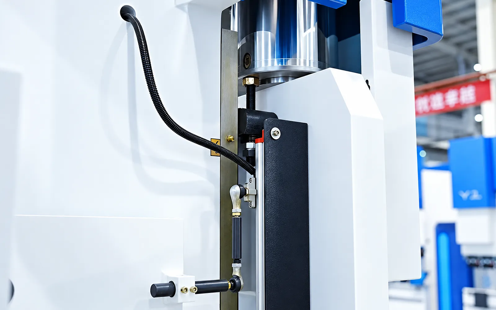
Linked control coordinates the ram axes of both machines during a tandem bend.
Confirm the controller, communication system and required linked or independent operating modes.
Linked backgauge control
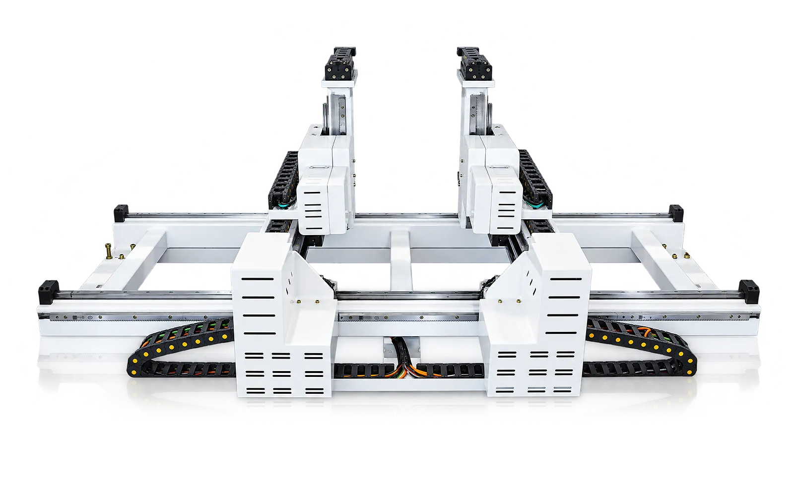
The tandem control package coordinates the backgauges for the selected operating mode.
Specify the positioning sequence together with communication-loss, stop and restart behavior.
03
Each worktable manages its own deflection while the part crosses the machine junction. Tool alignment and compensation must therefore be assessed as one continuous bend line.
Inspect angle and straightness at agreed positions, including the junction. Material, tooling and load distribution form part of that test.
Long-part handling
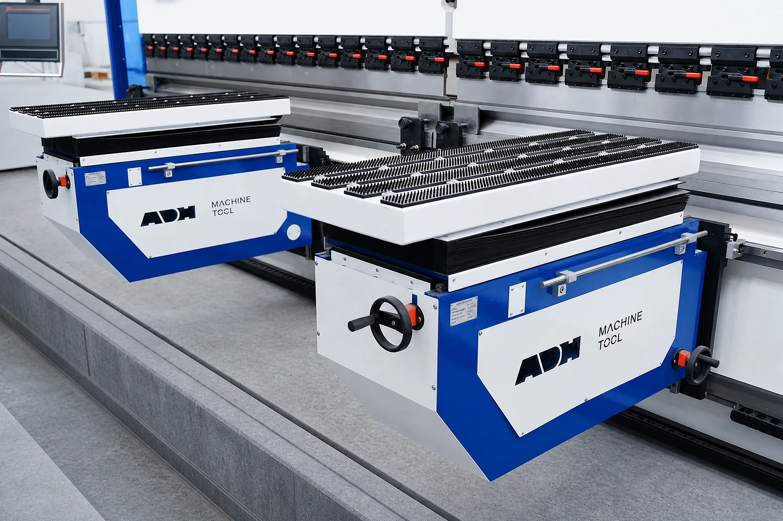
Long workpieces need a defined support and repositioning route.
Select follower support and lifting equipment around part weight, geometry and access.
Safeguards
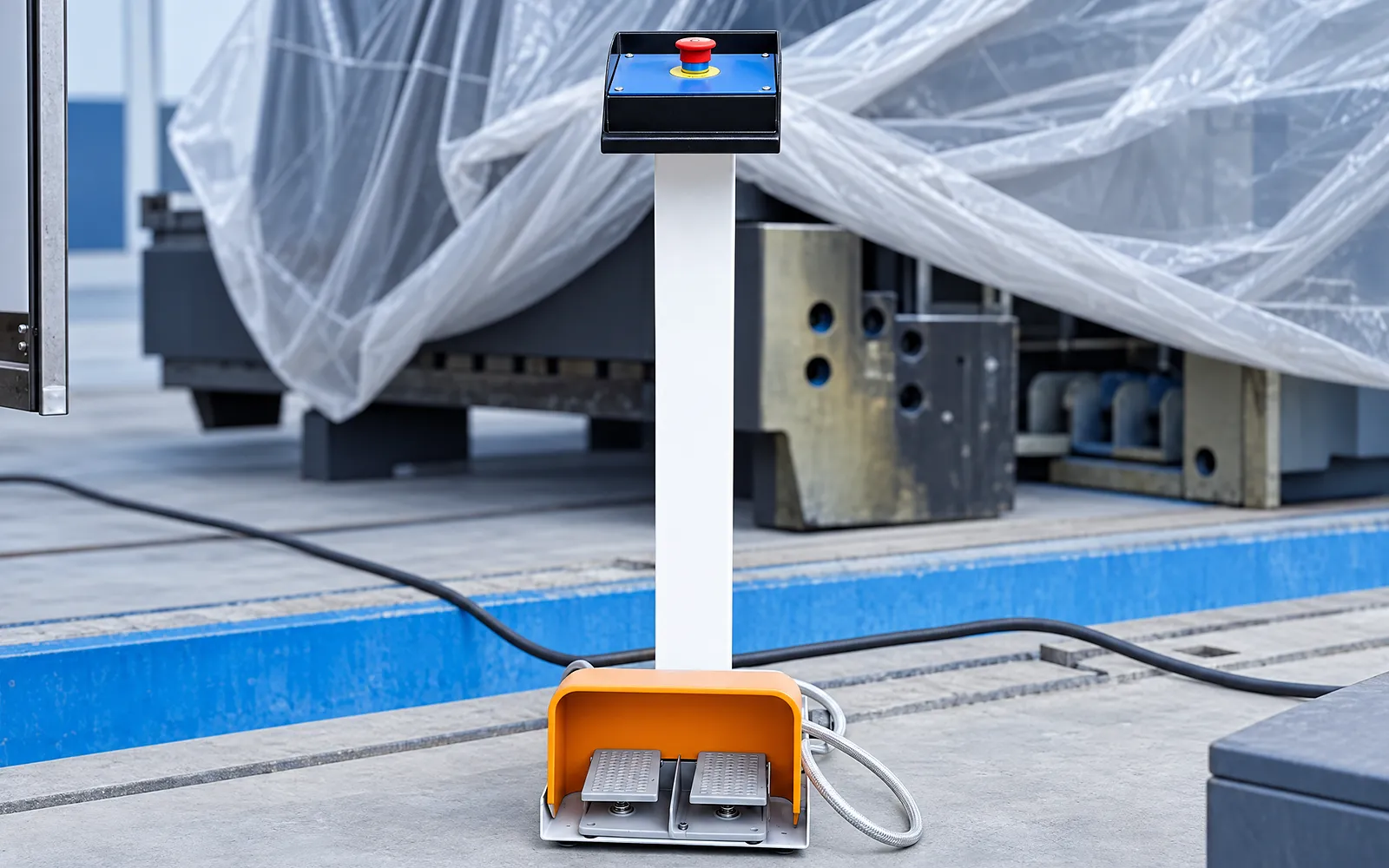
Operator positions and mode changes must be considered across the tandem installation.
Review perimeter protection, emergency stops, decoupling and recovery logic for the delivered system.
05
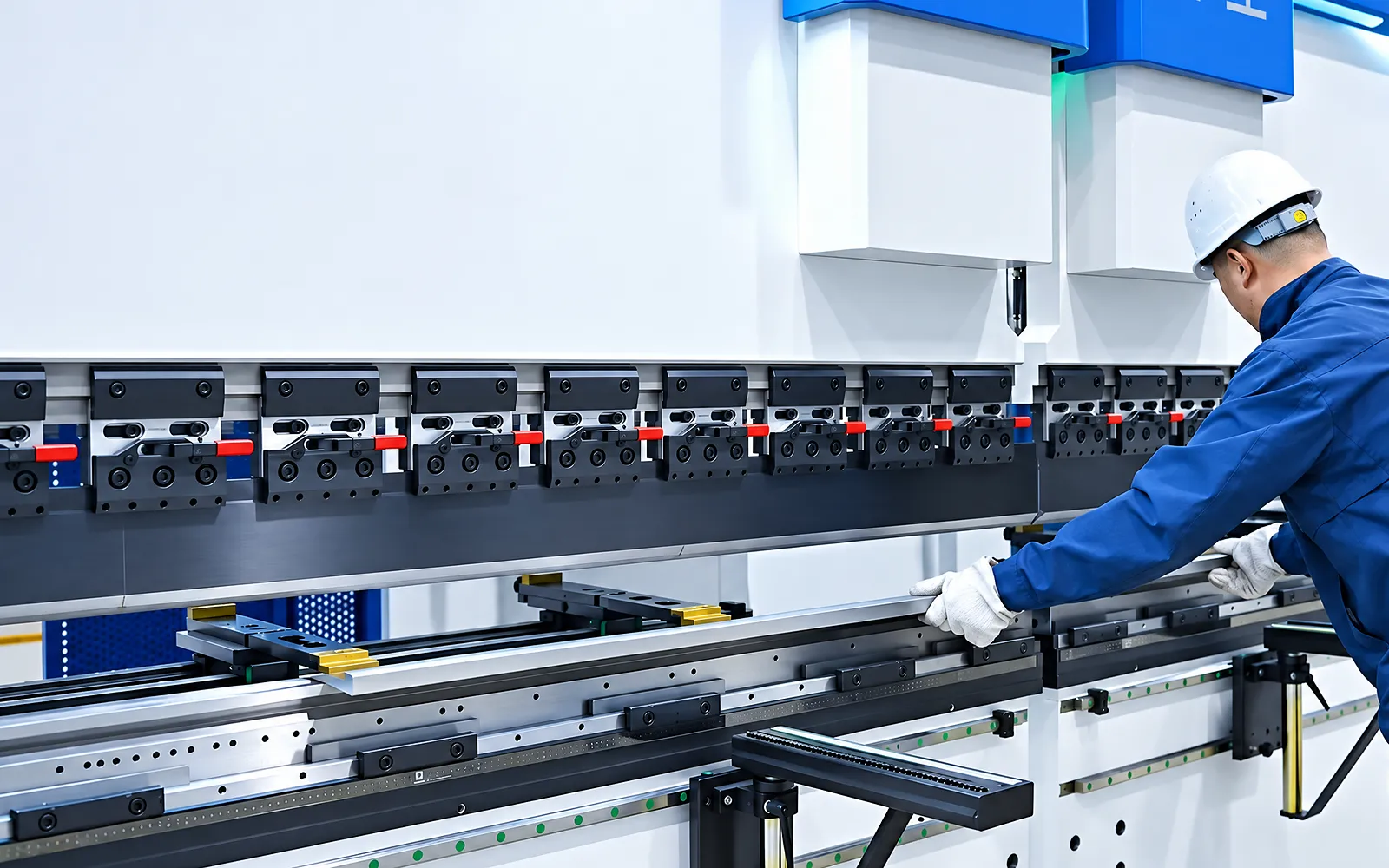
The trial should exercise linked motion, tooling, compensation and the actual support arrangement. It also shows how the part enters, turns and leaves the line.
Use the agreed drawing, material and inspection method. Record the configuration and operating mode used for the test.
Tandem engineering
Specify the matched machines and their shared operating requirements as one tandem installation.
The architecture uses matched electro-hydraulic hosts, tandem coordination, independent crowning and project-defined operating modes.
Machine pair, force, length, controller, bus, axes, tooling, support, guarding, foundation and independent mode are selected together.
Combined dimensions, synchronization tolerance, junction, handling and acceptance require a dedicated project sheet.
Related machines & selection
Through the machine lifecycle
Find the training, maintenance guidance and parts support your team needs. Services and availability are confirmed for your machine and location.
Before start-up
Prepare utilities, lifting and the installation area, then coordinate start-up and handover.
Review installation supportBefore production
Build the operator, programming and maintenance skills required for your delivered machine.
Explore trainingIn operation
Get support with the machine model, serial number and a clear description of the issue.
Request technical supportPlanned spares
Identify your machine and component so our team can check compatibility and availability.
Request service or partsSelf-service
Find video guidance for operating and maintaining your ADH machine. Check relevance to your model and configuration.
Browse support videosContract scope
Your quotation or contract defines included services, warranty, exclusions and responsibilities.
Review service scopeSee equipment options for the parts your industry produces.
Project enquiry
Tell us what you want to make or improve. Technical details and drawings can follow.
Contact ADH
Name, email and a short description are enough to begin.