
Best for
Deflection compensation across the bend length
Press Brake Upgrade
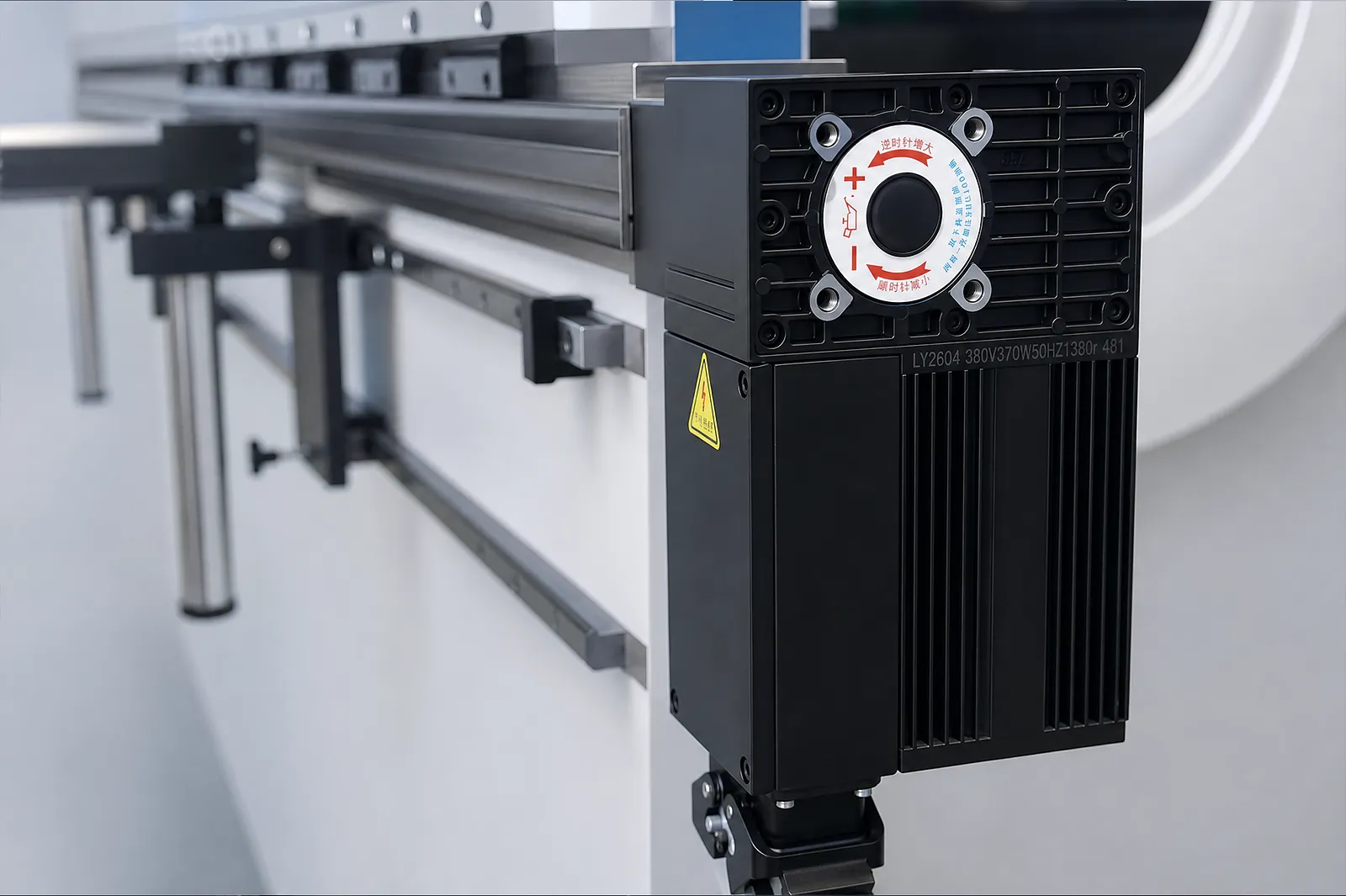
Crowning compensates for deflection across the bend length. Select manual, CNC or WILA-integrated adjustment from the bed, tooling, load and controller.
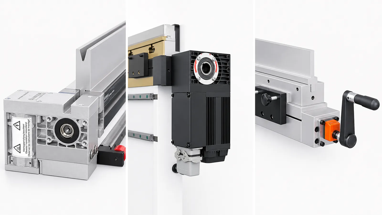
Best for
Deflection compensation across the bend length
Compare
Manual, CNC and WILA-integrated adjustment
Confirm
Bed, tooling, controller and acceptance method
Information Needed
Describe the bend length, material, tooling, force distribution and variation the compensation must address.
01 / BEND
Record material, bend length, tooling, load distribution and observed angle variation.
02 / CONTROL
Compare manual, CNC-driven and tooling-integrated adjustment by changeover and control needs.
03 / INTERFACE
List bed geometry, holders, controller output, adjustment range and installation access.
Crowning options
Select the method from part changes, adjustment workflow and the angle check.
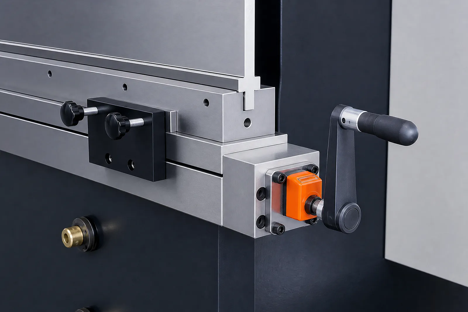
Use manual adjustment for a defined setup; verify bed and tooling interfaces.
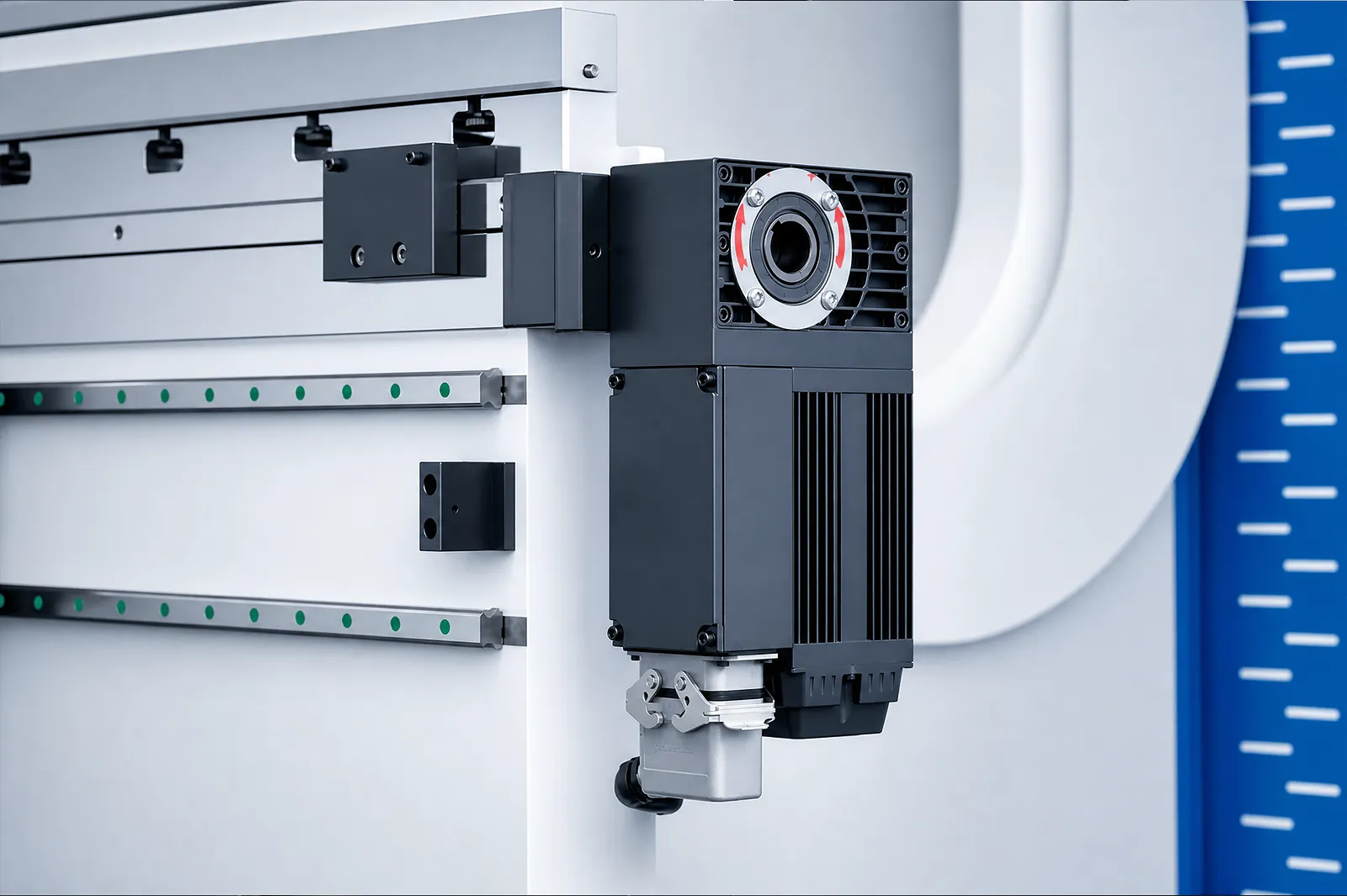
Use CNC adjustment when the controller and compensation workflow support the bend program.
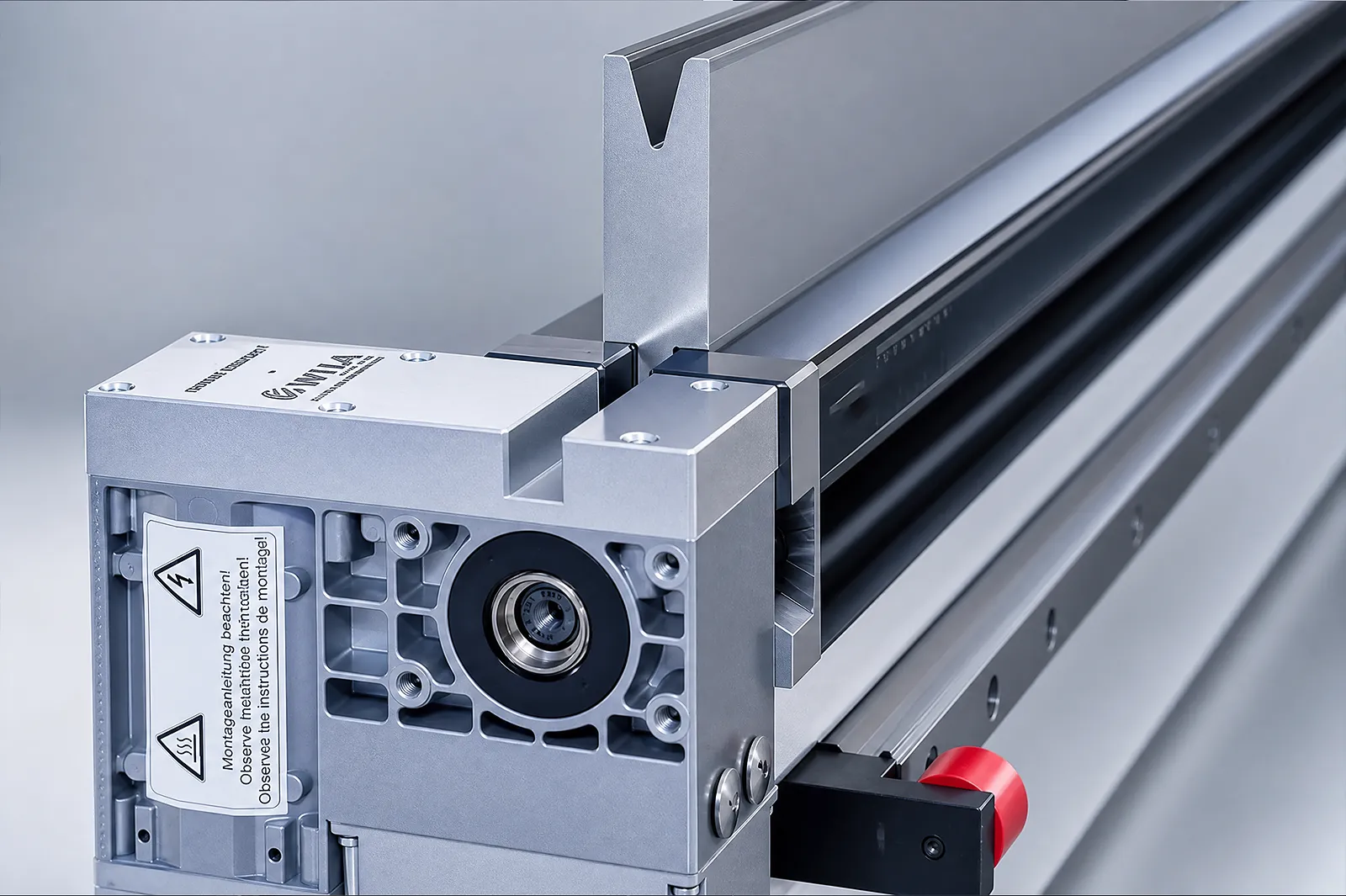
Use WILA holders and crowning when the tool interface and compensation method match.
Before You Order
Confirm that the frame, bed, tooling, controller and workpiece suit the selected crowning method.
Upgrade path
Identify the production problem, check compatibility, then agree installation and acceptance.
STEP 01
Record machine, controller, interfaces, photos, workflow and the production issue to solve.
STEP 02
Connect workpieces, process, operator tasks, output and site conditions to the upgrade.
STEP 03
Review mechanical, electrical, control, software, safety and service interfaces.
STEP 04
Define installation, tests, acceptance, documentation, training and support responsibilities.
Before You Contact ADH
Compatibility depends on table and ram geometry, controller, load, tooling and the bending application.
Check bed, holders, controller, installation space and compensation method.
Send model, working length, tooling, material range, typical parts and angle variation.
Compare table/ram, load, controller, tooling and the agreed straightness or angle check.
Name crowning method, hardware, controller integration, calibration, tests and service terms.
Project enquiry
Tell us what you want to make or improve. Technical details and drawings can follow.
Contact ADH
Name, email and a short description are enough to begin.