
01
Material and force
Provide material grade, tensile strength, thickness range, maximum bend length and the force calculation for the selected die opening.
Press Brake | WC67K/E Series
Torsion-bar synchronization and programmable backgauge positioning for straightforward, repeatable bending.
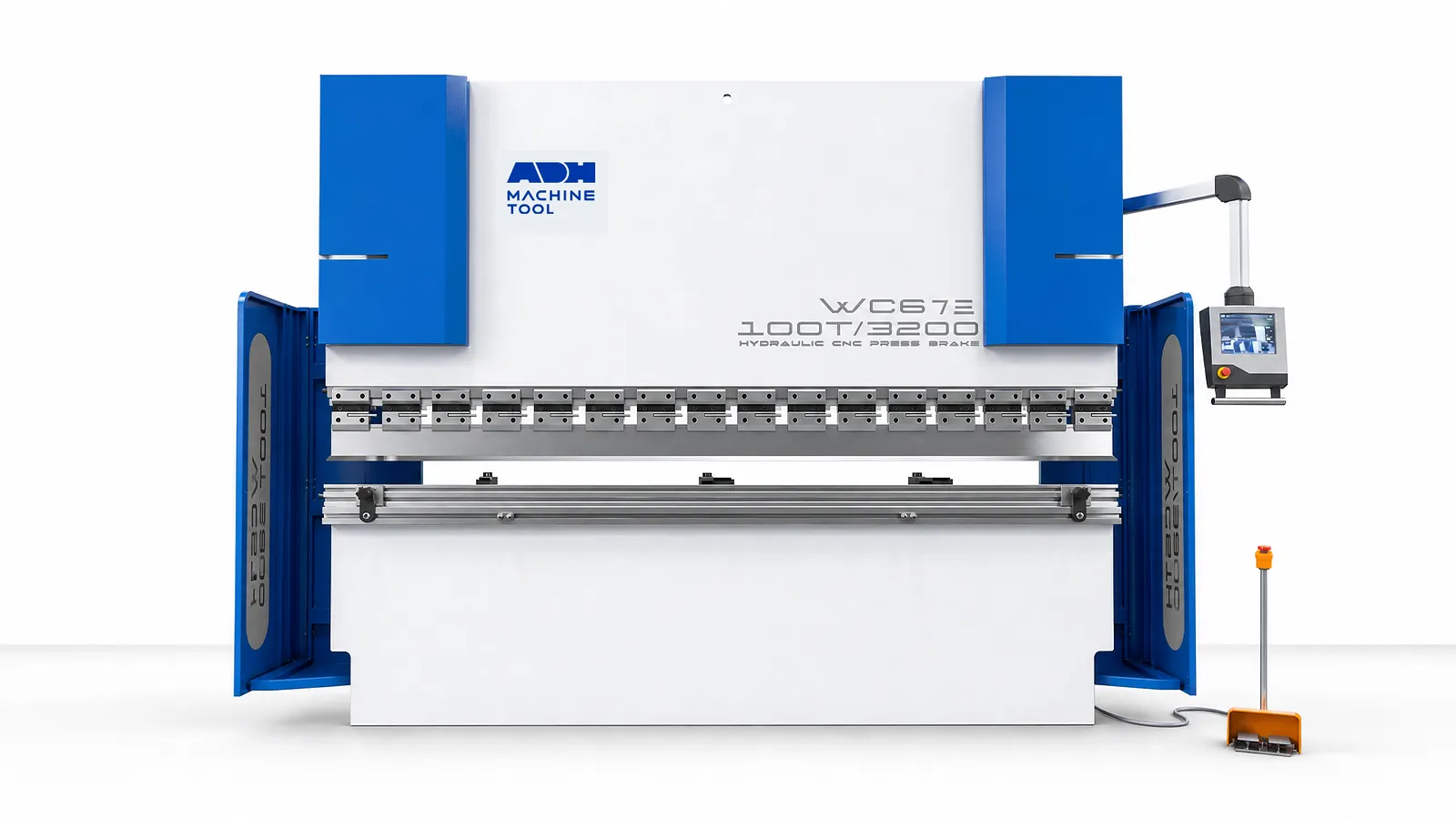
Technical specifications
The WC67K-30T/1600 delivers 300 kN over a 1,600 mm bending length, with 335 mm open height and a machine weight of 2.1 t. Select a WC67K or WC67K/E model below to check the opening, motor, pump and dimensions for your installation.
| Model | Bending Force | Bending Length | Oil Tank | Approach Speed | Working Speed | Return Speed | X Stroke | X Speed | Column Distance | Throat Depth | Ram Stroke | Open Height | Main Motor | Pump | Weight | Overall Dimensions |
|---|---|---|---|---|---|---|---|---|---|---|---|---|---|---|---|---|
| Unit | kN | mm | L | mm/s | mm/s | mm/s | mm | mm/s | mm | mm | mm | mm | kW | ml/r | t | L×W×H mm |
| WC67K-30t/1600 | 300 | 1600 | 80 | 120 | 17 | 160 | 600 | 150 | 1300 | 200 | 80 | 335 | 5.5 | 11 | 2.1 | 1800×1200×1700 |
| WC67K/E-30t/2000 | 300 | 2000 | 100 | 140 | 17 | 160 | 600 | 150 | 1600 | 200 | 80 | 335 | 5.5 | 11 | 2200×1200×1700 | |
| WC67K/E-40t/2500 | 400 | 2500 | 170 | 110 | 15 | 90 | 600 | 150 | 2030 | 250 | 100 | 355 | 5.5 | 13 | 2700×1200×1900 | |
| WC67K-63t/2500 | 630 | 2500 | 170 | 100 | 10 | 70 | 600 | 150 | 2050 | 250 | 120 | 370 | 5.5 | 13 | 4 | 2500×1350×2282 |
| WC67K/E-80t/2500 | 800 | 2500 | 170 | 110 | 10 | 80 | 600 | 150 | 2050 | 250 | 120 | 380 | 5.5 | 16 | 2500×1400×2150 | |
| WC67K/E-100t/2500 | 1000 | 2500 | 260 | 90 | 7.5 | 70 | 600 | 150 | 2050 | 320 | 160 | 430 | 7.5 | 16 | 2500×1500×2200 | |
| WC67K-100t/3200 | 1000 | 3200 | 260 | 100 | 7.5 | 70 | 600 | 150 | 2510 | 320 | 160 | 430 | 7.5 | 16 | 6.7 | 3200×1500×2300 |
| WC67E-100t/4000 | 1000 | 4000 | 260 | 120 | 7.5 | 70 | 600 | 150 | 3100 | 420 | 160 | 430 | 7.5 | 16 | 4000×1500×2400 | |
| WC67K-100t/4000 | 1000 | 4000 | 260 | 120 | 7.5 | 70 | 600 | 150 | 3100 | 420 | 160 | 430 | 7.5 | 16 | 8.4 | 4000×1500×2400 |
| WC67K/E-125t/2500 | 1250 | 2500 | 260 | 90 | 7 | 65 | 600 | 150 | 2050 | 320 | 160 | 430 | 7.5 | 16 | 2570×1620×2450 | |
| WC67K-125t/3200 | 1250 | 3200 | 260 | 95 | 7 | 65 | 600 | 150 | 2510 | 320 | 160 | 430 | 7.5 | 16 | 7.1 | 3200×1600×2350 |
| WC67E-125t/4000 | 1250 | 4000 | 260 | 110 | 7 | 65 | 600 | 150 | 3100 | 420 | 160 | 430 | 7.5 | 16 | 4000×1750×2590 | |
| WC67K-125t/4000 | 1250 | 4000 | 260 | 110 | 7 | 65 | 600 | 150 | 3100 | 420 | 160 | 430 | 7.5 | 16 | 9 | 4000×1750×2590 |
| WC67K/E-125t/5000 | 1250 | 5000 | 260 | 120 | 7 | 65 | 600 | 150 | 3800 | 320 | 160 | 430 | 7.5 | 16 | 11.5 | 5000×1600×2680 |
| WC67K/E-125t/6000 | 1250 | 6000 | 260 | 130 | 7 | 65 | 600 | 150 | 4800 | 320 | 160 | 430 | 7.5 | 16 | 14.6 | 6000×1600×2820 |
| WC67K/E-160t/2500 | 1600 | 2500 | 260 | 110 | 7 | 75 | 600 | 150 | 2050 | 350 | 200 | 480 | 11 | 20 | 2500×1650×2700 | |
| WC67K-160t/3200 | 1600 | 3200 | 260 | 110 | 7 | 75 | 600 | 150 | 2510 | 350 | 200 | 480 | 11 | 20 | 9.8 | 3200×1650×2800 |
| WC67K-160t/4000 | 1600 | 4000 | 260 | 110 | 7 | 75 | 600 | 150 | 3100 | 350 | 200 | 480 | 11 | 20 | 11.1 | 4000×1650×2800 |
| WC67K/E-160t/5000 | 1600 | 5000 | 260 | 120 | 7 | 75 | 600 | 150 | 3800 | 350 | 200 | 480 | 11 | 20 | 13.5 | 5000×1750×3100 |
| WC67K/E-160t/6000 | 1600 | 6000 | 260 | 120 | 7 | 75 | 600 | 150 | 4800 | 350 | 200 | 480 | 11 | 20 | 16.5 | 6000×1750×3300 |
| WC67K-200T/3200 | 2000 | 3200 | 435 | 100 | 8.5 | 65 | 600 | 150 | 2510 | 350 | 200 | 480 | 15 | 32 | 11.4 | 3200×1650×2800 |
| WC67K-200T/4000 | 2000 | 4000 | 435 | 100 | 8.5 | 65 | 600 | 150 | 3100 | 350 | 200 | 480 | 15 | 32 | 12.7 | 4000×1650×2800 |
| WC67K/E-200T/5000 | 2000 | 5000 | 435 | 100 | 8.5 | 65 | 600 | 150 | 3800 | 350 | 200 | 480 | 15 | 32 | 16.4 | 5000×1950×3100 |
| WC67K/E-200T/6000 | 2000 | 6000 | 435 | 100 | 8.5 | 65 | 600 | 150 | 4800 | 350 | 200 | 480 | 15 | 32 | 21.5 | 6000×1950×3100 |
| WC67K-250T/3200 | 2500 | 3200 | 435 | 100 | 8 | 75 | 600 | 150 | 2600 | 400 | 250 | 580 | 18.5 | 40 | 15.5 | 3300×2100×3150 |
| WC67K-250T/4000 | 2500 | 4000 | 435 | 100 | 8 | 75 | 600 | 150 | 3100 | 400 | 250 | 580 | 18.5 | 40 | 17.2 | 4000×2100×3150 |
| WC67K/E-250T/5000 | 2500 | 5000 | 435 | 100 | 8 | 75 | 600 | 150 | 3800 | 400 | 250 | 580 | 18.5 | 40 | 21 | 5000×2100×3200 |
| WC67K/E-250T/6000 | 2500 | 6000 | 540 | 100 | 8 | 75 | 600 | 150 | 4800 | 400 | 250 | 580 | 18.5 | 40 | 23.5 | 6000×2100×3200 |
| WC67K-300T/3200 | 3000 | 3200 | 540 | 90 | 8 | 75 | 600 | 150 | 2600 | 400 | 250 | 580 | 18.5 | 40 | 17 | 3200×2200×3200 |
| WC67K-300T/4000 | 3000 | 4000 | 540 | 100 | 8 | 75 | 600 | 150 | 3100 | 400 | 250 | 580 | 18.5 | 40 | 18.8 | 4000×2200×3200 |
| WC67K/E-300T/5000 | 3000 | 5000 | 540 | 110 | 8 | 75 | 600 | 150 | 3800 | 400 | 250 | 580 | 18.5 | 40 | 24 | 5000×2200×3200 |
| WC67K/E-300T/6000 | 3000 | 6000 | 540 | 130 | 8 | 75 | 600 | 150 | 4800 | 400 | 250 | 580 | 18.5 | 40 | 28 | 6000×2200×3200 |
| WC67K/E-400T/3200 | 4000 | 3200 | 540 | 90 | 7 | 75 | 600 | 150 | 2500 | 400 | 250 | 580 | 22 | 50 | 19.3 | 3300×2400×3200 |
| WC67K/E-400T/4000 | 4000 | 4000 | 540 | 90 | 7 | 75 | 600 | 150 | 3100 | 400 | 250 | 580 | 22 | 50 | 23.8 | 4000×2400×3200 |
| WC67K/E-400T/5000 | 4000 | 5000 | 550 | 90 | 7 | 75 | 850 | 150 | 3800 | 400 | 250 | 580 | 22 | 50 | 27.9 | 5000×2400×3200 |
| WC67K/E-400T/6000 | 4000 | 6000 | 550 | 90 | 7 | 75 | 850 | 150 | 4800 | 400 | 250 | 580 | 22 | 50 | 33 | 6000×2400×3200 |
Bending inputs
Start with material, geometry, tooling load and the positioning functions required for repeat production.
01
Provide material grade, tensile strength, thickness range, maximum bend length and the force calculation for the selected die opening.
02
Share flange dimensions, box depth, radius, bend sequence and the reference edges the backgauge must locate.
03
Define punch and die profiles, allowable line load, clamping method and the angle or dimensional tolerance to be inspected.
04
Record batch size, program changes, support needs, controller functions, guarding and destination requirements.
Machine in operation
Watch the NC Press Brake operating sequence, then compare its synchronization, positioning, tooling and safety systems below.
Watch on YouTube (opens in a new tab)Product systems
WC67K/E uses a mechanical torsion bar to synchronize the ram. Programmed positioning, tool selection and the operator workflow determine how it fits your bending work.
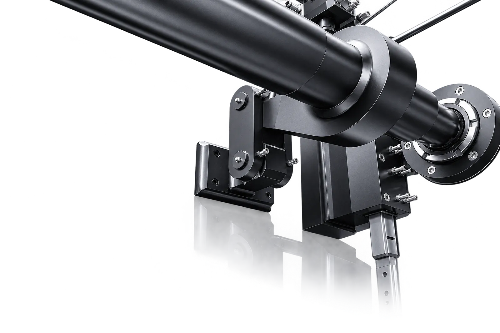
Torsion bar
The torsion bar links the two ram sides in this NC architecture.
This differs from independent Y1/Y2 feedback control; assess it against the required tolerances.
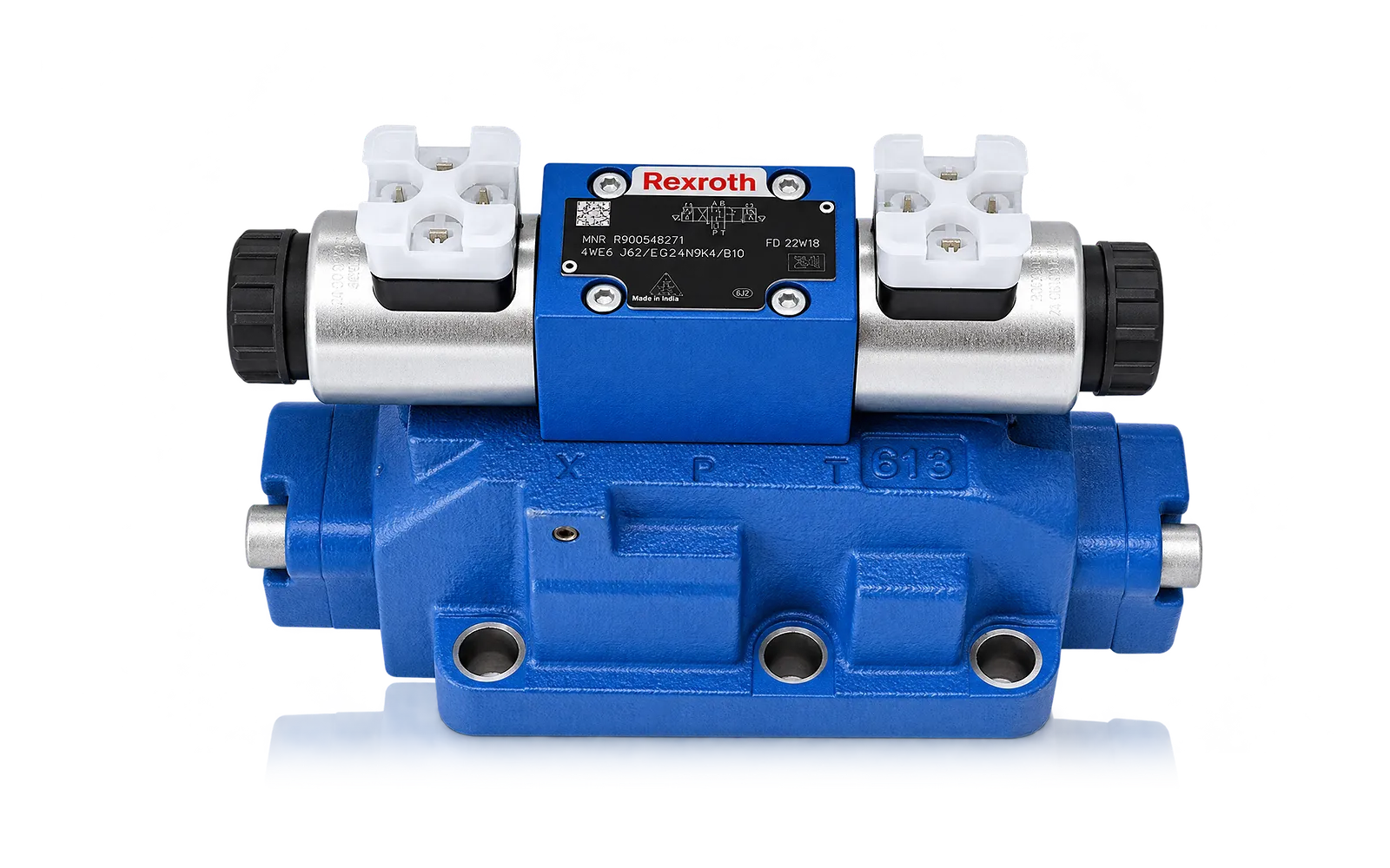
Hydraulic drive
Hydraulic cylinders drive the ram, while mechanical stops establish its lower position.
Read force, stroke and working speeds from the selected WC67K/E model.
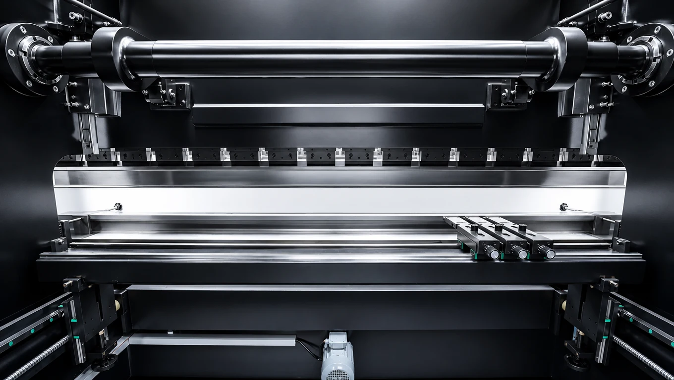
02
The X backgauge positions the reference edge for successive bends. The finger arrangement and available height or lateral adjustment affect access to the workpiece.
Check the shortest flange, return bends and required travel. R and Z functions depend on the positioning package.
03
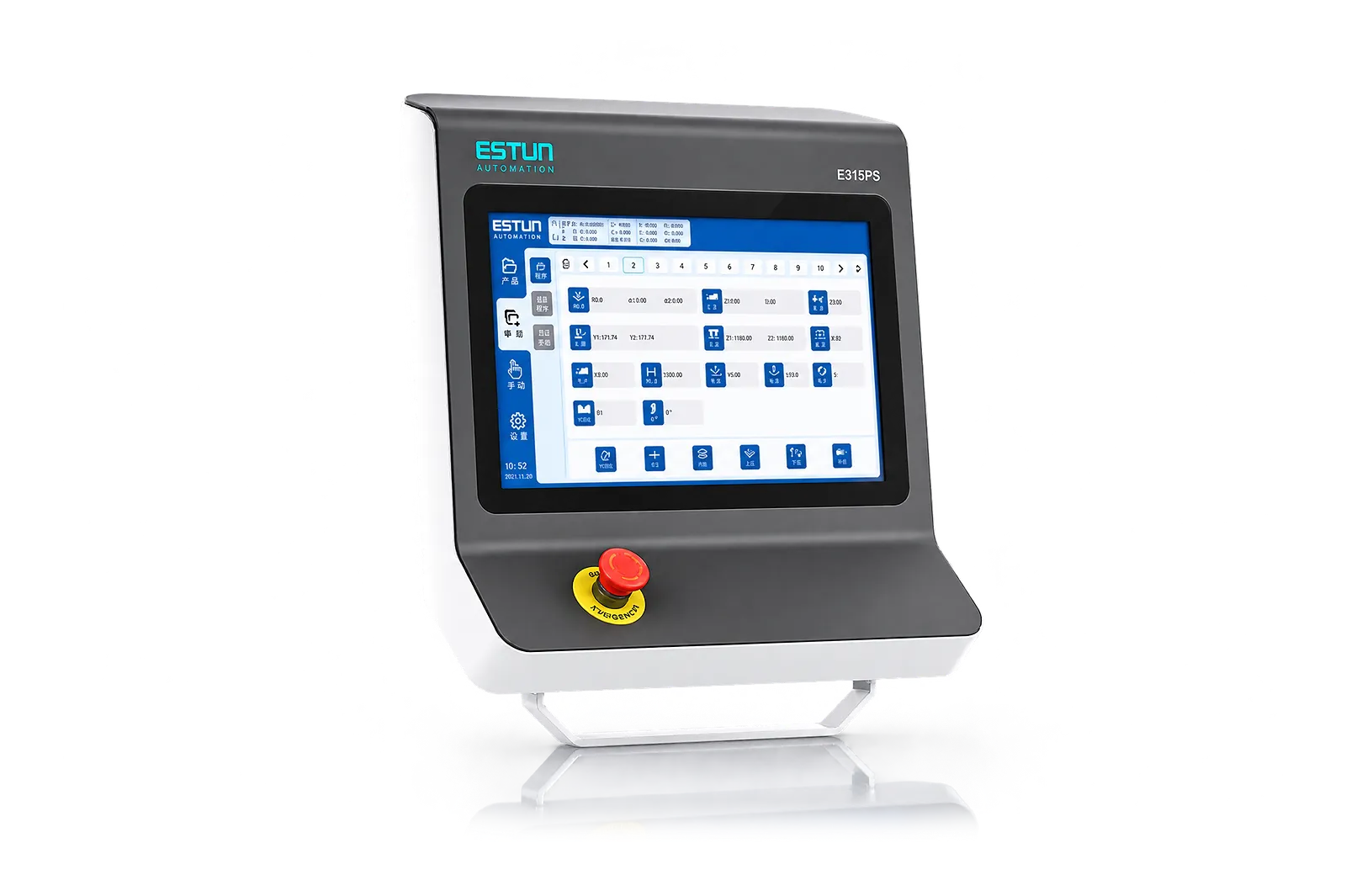
The NC controller manages the available positioning and program functions for repeated work. Its capabilities determine how operators enter, recall and adjust the job.
Review the supplied controller on your normal part sequence. Check which positions are programmed and which setup changes remain manual.
Tools
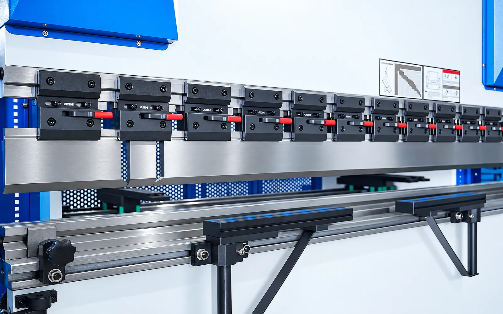
Punch profile, die opening and the tool interface determine forming geometry and load.
Specify tool set, clamp compatibility and load capacity for the actual part.
Compensation
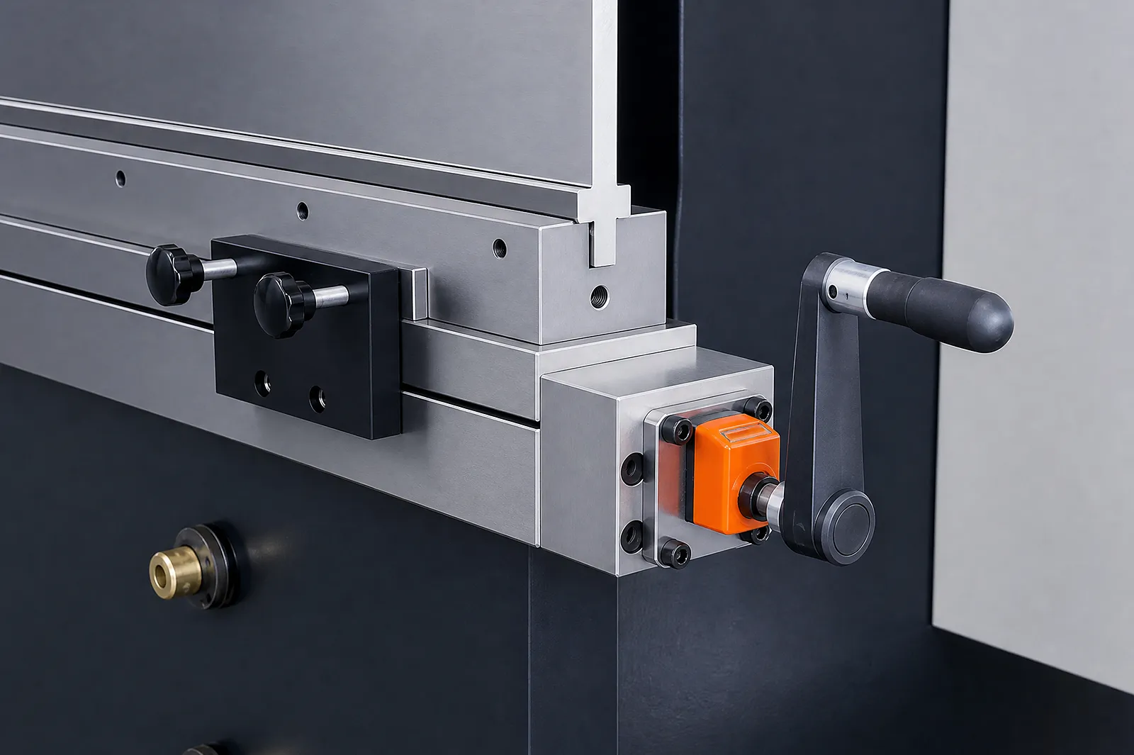
Compensation, where included, addresses deflection along the working length.
Review the required angle and straightness on the intended material and bend length.
Operator workflow
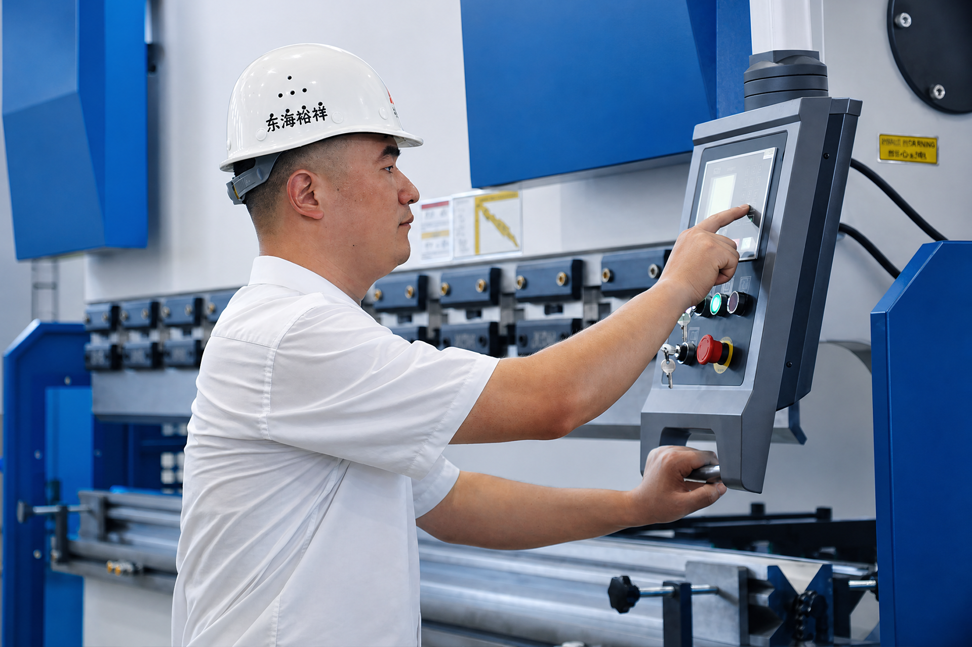
The operator positions, supports and reorients the part between bends.
Review emergency stops, travel limits, interlocks, foot controls and guarding for that workflow.
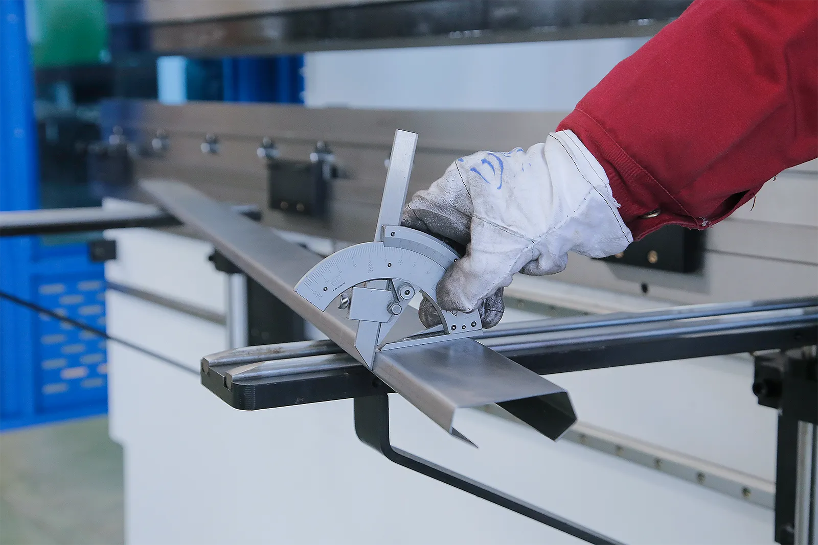
Part checks
A sample run shows how the selected machine, tools and handling method work together.
Agree the sample drawing and inspection method for the finished part.
Model range and options
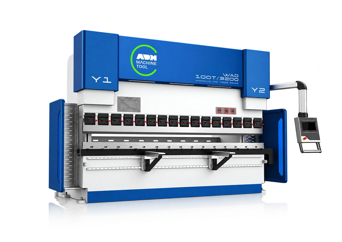
Use the WC67K/E model table for the machine reference; controller, positioning, tooling and safeguarding are finalized in the quotation.
Use the WC67K/E model rows for force, working length, speeds, strokes, opening, motor, pump, weight and dimensions.
Controller, R/Z positioning, crowning, quick clamping, front supports, optical protection and special tooling require quotation confirmation.
Confirm material strength, calculated force, tooling capacity, part access, tolerance, electrical supply and the complete safety package.
Related machines & selection
Through the machine lifecycle
Find the training, maintenance guidance and parts support your team needs. Services and availability are confirmed for your machine and location.
Before start-up
Prepare utilities, lifting and the installation area, then coordinate start-up and handover.
Review installation supportBefore production
Build the operator, programming and maintenance skills required for your delivered machine.
Explore trainingIn operation
Get support with the machine model, serial number and a clear description of the issue.
Request technical supportPlanned spares
Identify your machine and component so our team can check compatibility and availability.
Request service or partsSelf-service
Find video guidance for operating and maintaining your ADH machine. Check relevance to your model and configuration.
Browse support videosContract scope
Your quotation or contract defines included services, warranty, exclusions and responsibilities.
Review service scopeProject enquiry
Tell us what you want to make or improve. Technical details and drawings can follow.
Contact ADH
Name, email and a short description are enough to begin.