
01
Material and force
Provide material grade, strength, thickness, maximum bend length, V-opening and calculated force for the intended tools.
Press Brake | WADG Series
All-electric bending with servo motors and precision screws, for small- to medium-force work without a hydraulic power unit.
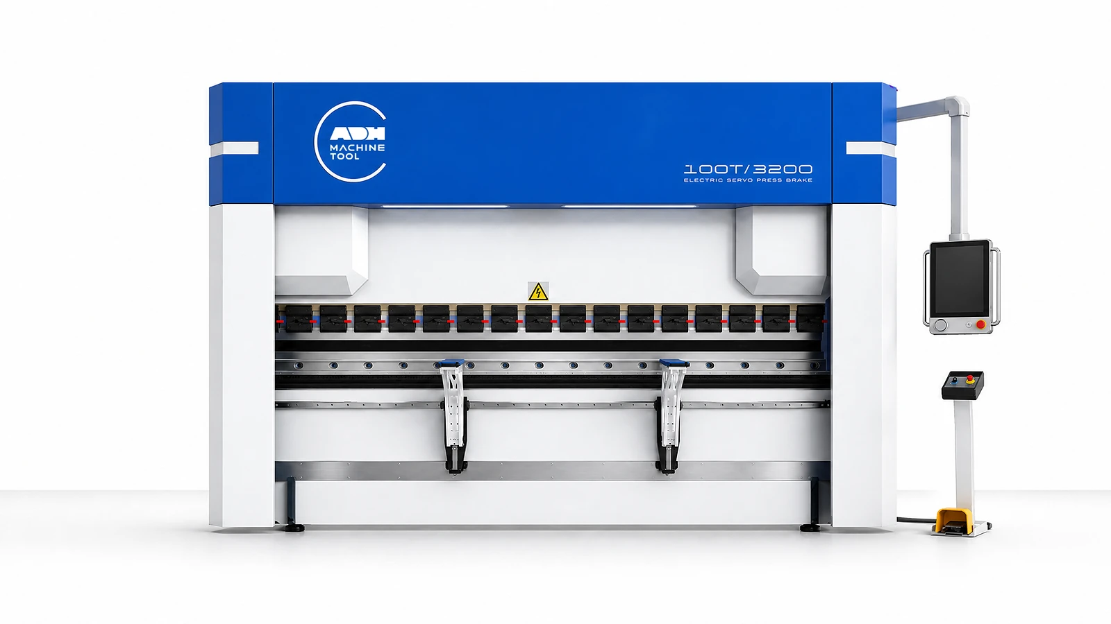
Technical specifications
The WADG-50T/1600 has a 200 mm ram stroke, 470 mm open height and two 20 kW main motors. Select a model below to compare its force, bending length, clearances and drive power against your tooling and handling arrangement.
| Model | Bending Force | Working Length | Approach Speed | Working Speed | Return Speed | X Stroke | X Speed | R Stroke | R Speed | Column Distance | Throat Depth | Ram Stroke | Open Height | Main Motor | Weight | Overall Dimensions |
|---|---|---|---|---|---|---|---|---|---|---|---|---|---|---|---|---|
| Unit | kN | mm | mm/s | mm/s | mm/s | mm | mm/s | mm | mm/s | mm | mm | mm | mm | kW | t | L×W×H mm |
| WADG-10T/500 | 100 | 500 | 180 | 0.15-30 | 180 | 200 | 400 | 80 | 200 | 510 | 200 | 150 | 420 | 6 | 0.8 | 640*980*1250 |
| WADG-20T/800 | 200 | 800 | 250 | 0.15-30 | 250 | 400 | 500 | 150 | 200 | 780 | 250 | 150 | 420 | 15 | 3.1 | 1200*1560*2450 |
| WADG-30T/1250 | 300 | 1250 | 250 | 0.15-30 | 250 | 400 | 500 | 150 | 200 | 900 | 250 | 150 | 420 | 20 | 4.1 | 1460*1660*2470 |
| WADG-40T/1300 | 400 | 1300 | 250 | 0.15-30 | 250 | 400 | 500 | 150 | 200 | 920 | 255 | 150 | 420 | 2X15 | 4.5 | 1700*2050*2280 |
| WADG-40T/1600 | 400 | 1600 | 250 | 0.15-30 | 250 | 400 | 500 | 150 | 200 | 1120 | 255 | 150 | 420 | 2X15 | 4.9 | 1700*2050*2280 |
| WADG-50T/1600 | 500 | 1600 | 250 | 0.15-30 | 250 | 400 | 500 | 150 | 200 | 1250 | 255 | 200 | 470 | 2×20 | 4.9 | 2200*2050*2280 |
| WADG-60T/2000 | 600 | 2000 | 250 | 0.15-30 | 250 | 500 | 500 | 150 | 200 | 1600 | 300 | 200 | 470 | 2X20 | 6 | 2700*2150*2380 |
| WADG-80T/2500 | 800 | 2500 | 200 | 0.15-30 | 200 | 500 | 500 | 150 | 200 | 2000 | 460 | 200 | 470 | 2X25 | 8.9 | 3000*2250*2380 |
| WADG-100T/3200 | 1000 | 3200 | 200 | 0.15-30 | 200 | 500 | 500 | 150 | 200 | 2700 | 460 | 200 | 470 | 2X25 | 10.7 | 4000*2450*2580 |
| WADG-160T/3200 | 1600 | 3200 | 200 | 0.15-30 | 200 | 500 | 500 | 150 | 200 | 2700 | 460 | 250 | 520 | 3X25 | 11.8 | 4000*2450*2780 |
Application fit
Select WADG from material, bend plan, batch pattern, tooling and operating environment.
01
Provide material grade, strength, thickness, maximum bend length, V-opening and calculated force for the intended tools.
02
Share geometry, flange, radius, sequence, angle target and acceptance check.
03
Define product mix, batch, cycle profile, program/tooling changes and handling or robot interface.
04
Confirm power, floor/service access, lubrication, controller, safeguarding and destination requirements.

Machine in operation
Watch the Electric Press Brake operating sequence, then compare its drive, feedback, tooling and safety systems below.
Product systems
WADG transfers servo-motor motion through a belt and screw drive to the ram. Match that drive, the positioning package and tooling to your production cycle.
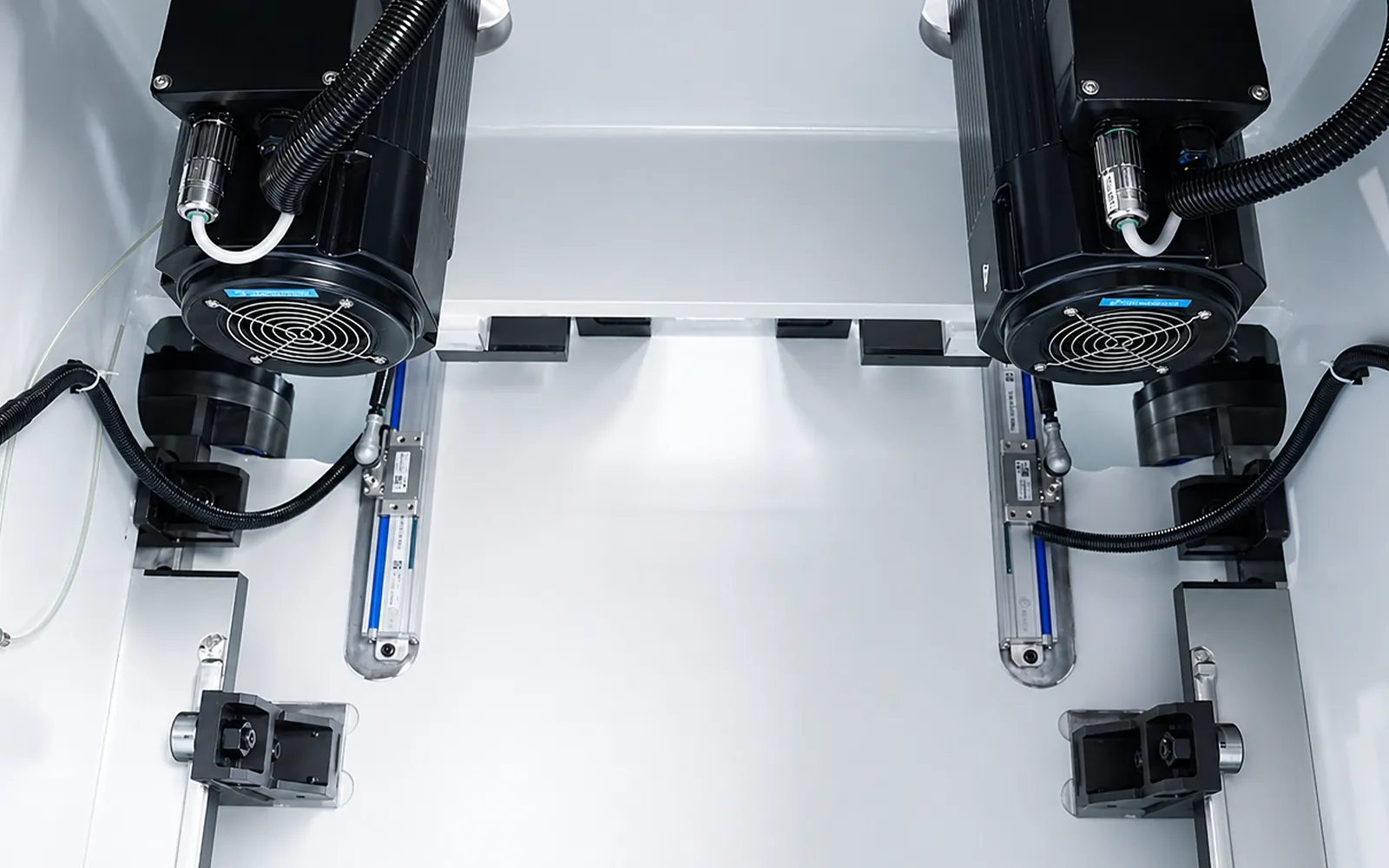
01
Servo motors drive the ram through a belt and precision screw system, without a hydraulic power unit. Independent Y1/Y2 feedback monitors the left and right drive positions.
Select force, travel and motion data from the exact WADG model. Required duty, tooling and load must be assessed together.
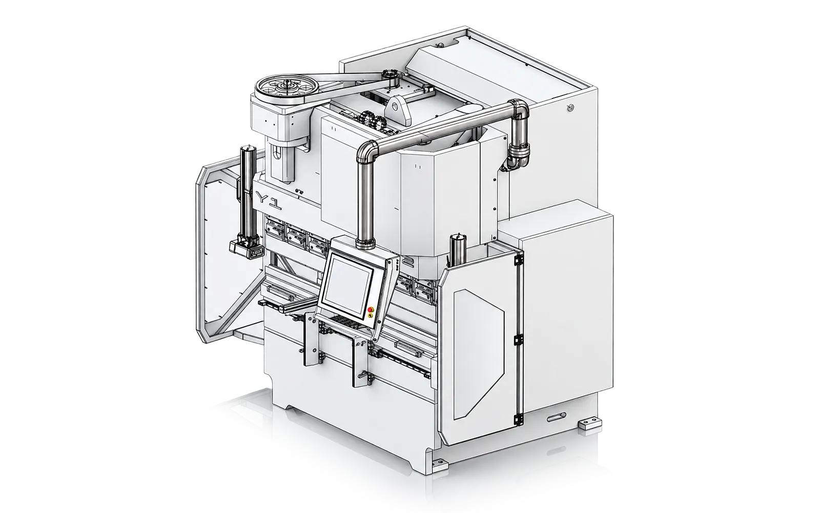
Frame and guidance
The frame and machined guides establish the relationship between drive, ram and worktable.
Review force, working length and tool loading as one structural setup.
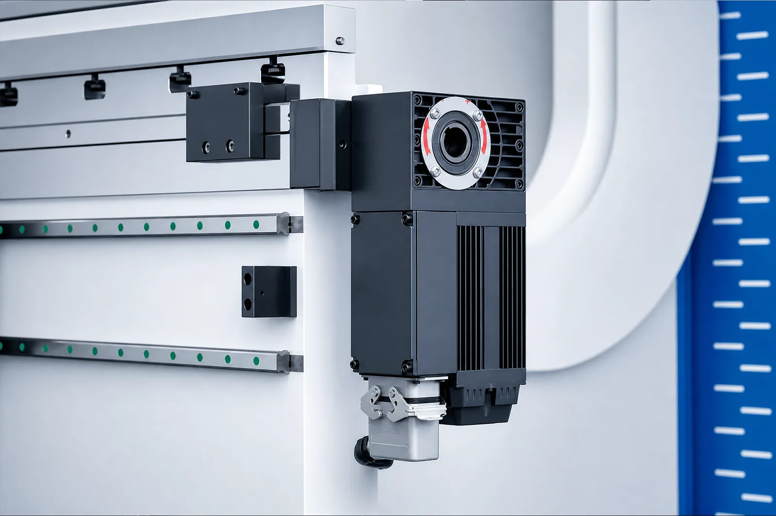
Compensation
The compensation arrangement addresses deflection for the selected bend length.
Review calibration and the loaded sample result alongside individual drive specifications.
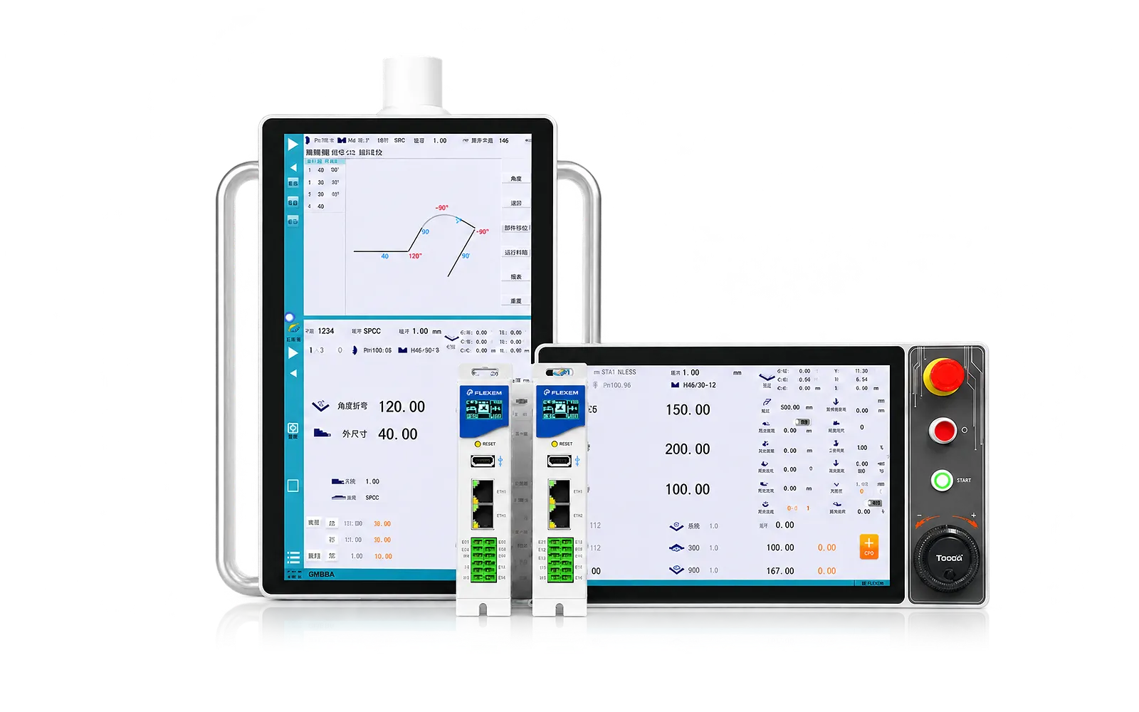
CNC
The CNC coordinates the bend program and the required positioning sequence.
Review controller functions, tool access and part reorientations. Angle measurement and robot interfaces are selectable options.
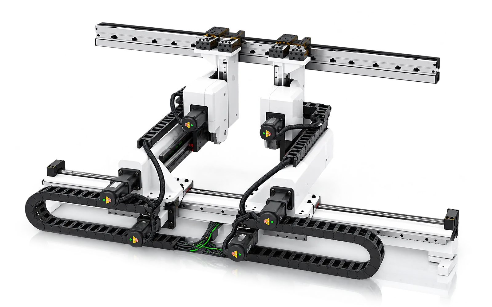
Backgauge positioning
The selected backgauge axes and finger arrangement determine how the workpiece is referenced.
Check each flange and return bend against the available positioning and tool clearance.
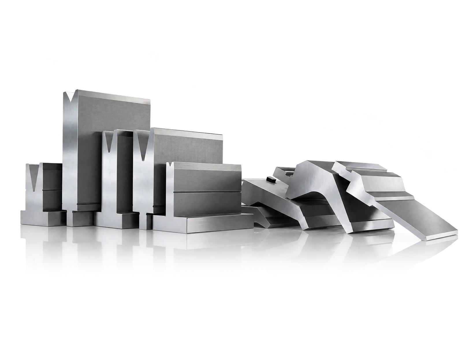
Tooling
Tool profiles and clamping establish the forming space and changeover method.
Match tooling capacity and the clamp interface to the intended part family.
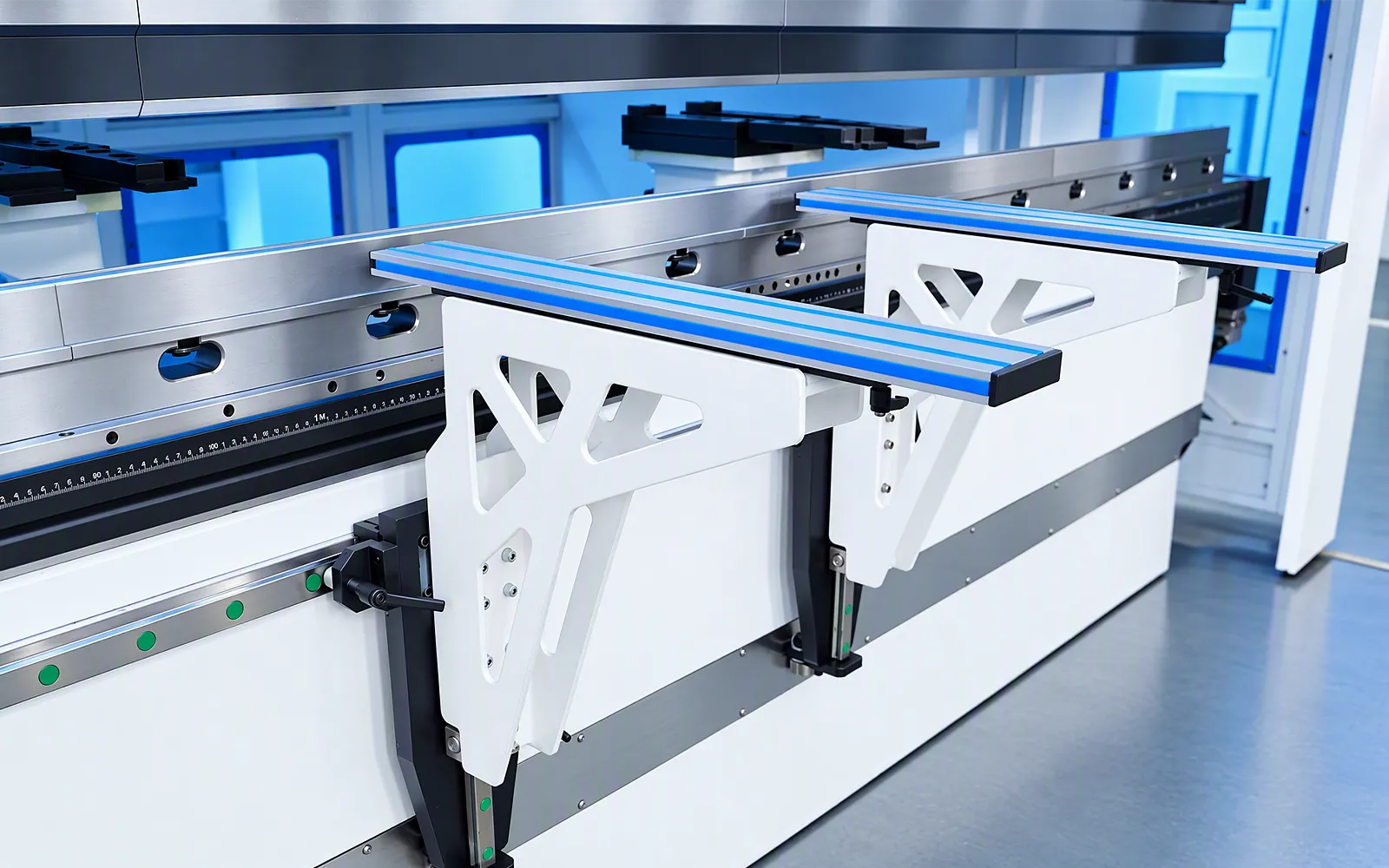
Part support
Front support and access affect how the operator holds and turns the workpiece.
Review support, safeguarding and any handling equipment required for the workflow.
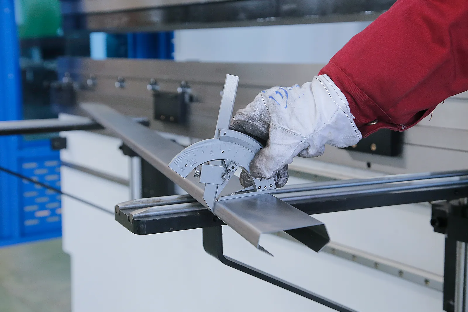
05
A representative run includes setup, positioning, bending and part handling. It provides a useful basis for evaluating an electric machine in the intended production cycle.
Agree material, drawing, inspection points and operating conditions. Check the finished angle and straightness together with the handling sequence.
Application planning
The supplied samples illustrate access and bend order but do not define material, thickness or inspection results.
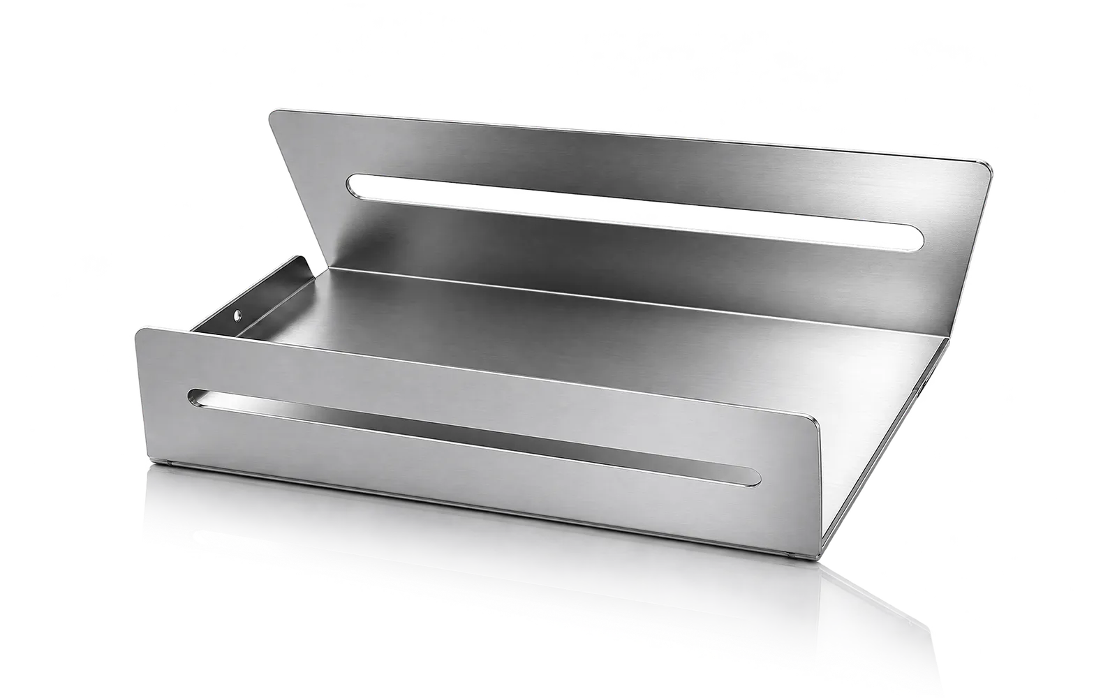
Bend sequence
Check flange access, return bends, tooling clearance and part support through each operation.
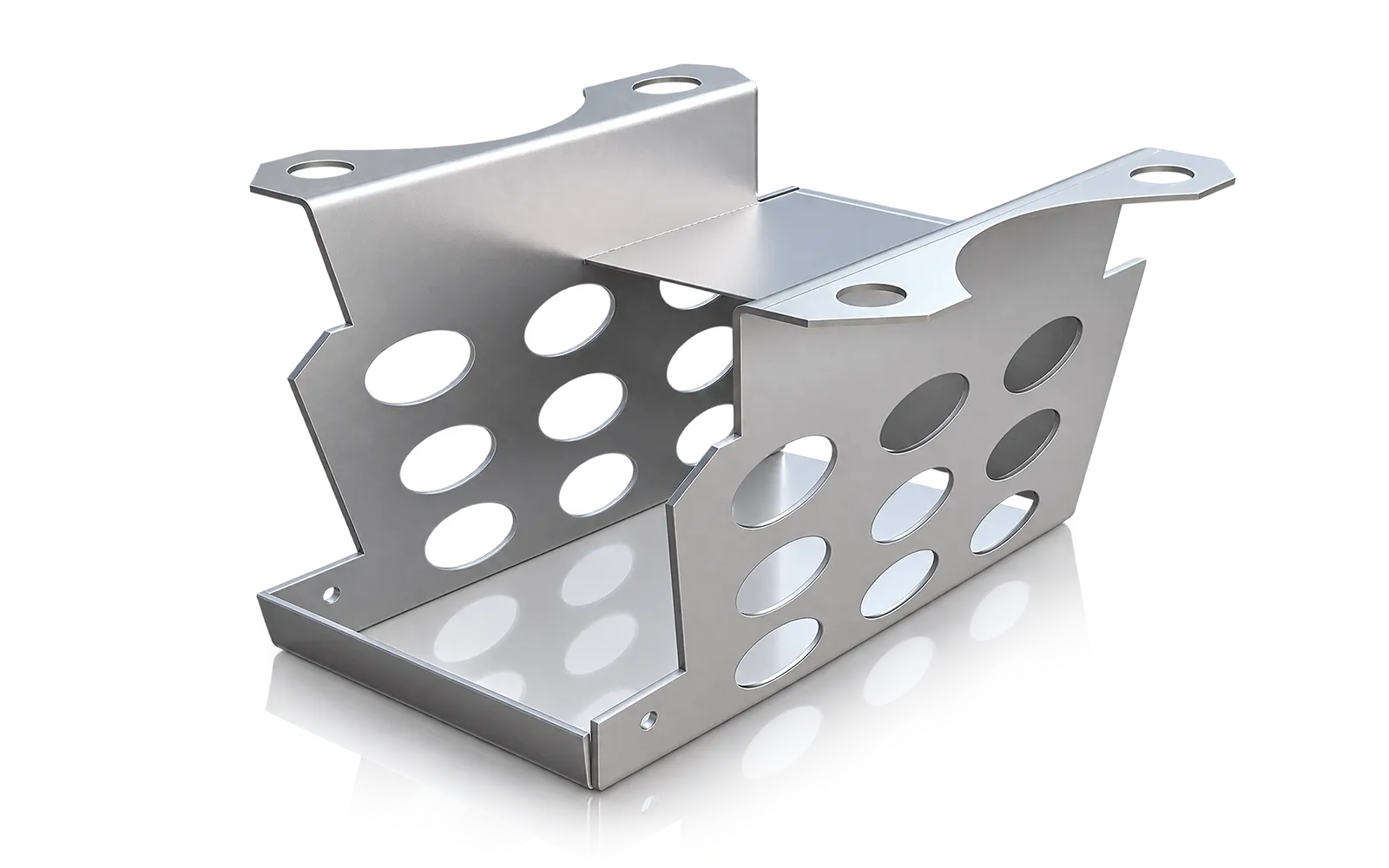
Part access
Confirm hole-to-bend relationships, rotation, grip or support points and the datum used for final inspection.
Configuration
Use the WADG model data for numeric selection; controller, tooling, safety and automation require project confirmation.
Use the WADG model rows from 10T/500 through 160T/3200 for force, length, speeds, axes, power, weight and dimensions.
Controller, axes, crowning, clamping, angle measurement, robot interface, optical protection and tooling vary by configuration.
Confirm force calculation, drive duty, lubrication, tooling load, part support, sample, power and safeguarding.
Related machines & selection
Through the machine lifecycle
Find the training, maintenance guidance and parts support your team needs. Services and availability are confirmed for your machine and location.
Before start-up
Prepare utilities, lifting and the installation area, then coordinate start-up and handover.
Review installation supportBefore production
Build the operator, programming and maintenance skills required for your delivered machine.
Explore trainingIn operation
Get support with the machine model, serial number and a clear description of the issue.
Request technical supportPlanned spares
Identify your machine and component so our team can check compatibility and availability.
Request service or partsSelf-service
Find video guidance for operating and maintaining your ADH machine. Check relevance to your model and configuration.
Browse support videosContract scope
Your quotation or contract defines included services, warranty, exclusions and responsibilities.
Review service scopeProject enquiry
Tell us what you want to make or improve. Technical details and drawings can follow.
Contact ADH
Name, email and a short description are enough to begin.