
01
Material and force
Provide material grade, thickness range, maximum bend length, part envelope, flange geometry, radius and the force/tooling calculation.
CNC Press Brake · WADE Series
Programmed bending with closed-loop Y1/Y2 control. WADE offers 50T/1300 to 300T/6000 models and a choice of ACS controllers.
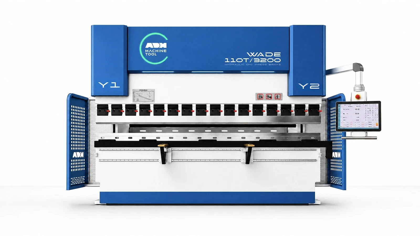
Technical specifications
Select the WADE model to check its bending force, stroke speeds and matching motor and pump. Use the additional drive options below when comparing a named servo package. Specify the ACS controller and required axes with the chosen machine.
| Model | Bending Force | Bending Length | Approach Speed | Working Speed | Return Speed | X Stroke | X Speed | R Stroke | R Speed | Column Distance | Throat Depth | Ram Stroke | Open Height | Main motor | Pump displacement | Weight | Overall Dimensions |
|---|---|---|---|---|---|---|---|---|---|---|---|---|---|---|---|---|---|
| Unit | kN | mm | mm/s | mm/s | mm/s | mm | mm/s | mm | mm/s | mm | mm | mm | mm | kW | ml/r | t | L×W×H mm |
| WADE-70T/2500 | 700 | 2500 | 220 | 0–15 | 200 | 500 | 400 | 200 | 200 | 2050 | 300 | 150 | 460 | 7.5 | 13 | 4.4 | 3100 × 1600 × 2400 |
| WADE-110T/3200 | 1100 | 3200 | 220 | 0–15 | 200 | 500 | 400 | 200 | 200 | 2700 | 400 | 200 | 480 | 11 | 20 | 7.2 | 3750 × 2202 × 2700 |
| WADE-110T/4100 | 1100 | 4100 | 220 | 0–15 | 200 | 500 | 400 | 200 | 200 | 3600 | 400 | 200 | 480 | 11 | 20 | 8.7 | 4700 × 1800 × 2700 |
| WADE-135T/3200 | 1350 | 3200 | 200 | 0–13 | 160 | 500 | 400 | 200 | 200 | 2700 | 400 | 200 | 480 | 11 | 20 | 8.3 | 3800 × 1800 × 2700 |
| WADE-135T/4100 | 1350 | 4100 | 200 | 0–13 | 160 | 500 | 400 | 200 | 200 | 3600 | 400 | 200 | 480 | 11 | 20 | 9.9 | 4700 × 1800 × 2700 |
| WADE-170T/3200 | 1700 | 3200 | 160 | 0–12 | 125 | 500 | 400 | 200 | 200 | 2700 | 450 | 200 | 480 | 15 | 25 | 10.3 | 3800 × 2000 × 2800 |
| WADE-170T/4100 | 1700 | 4100 | 160 | 0–12 | 125 | 500 | 400 | 200 | 200 | 3600 | 450 | 200 | 480 | 15 | 25 | 12.0 | 4700 × 2000 × 2800 |
| WADE-170T/5000 | 1700 | 5000 | 160 | 0–12 | 125 | 500 | 400 | 200 | 200 | 4000 | 450 | 200 | 480 | 15 | 25 | 13.4 | 5600 × 2000 × 3160 |
| WADE-170T/6000 | 1700 | 6000 | 160 | 0–12 | 125 | 500 | 400 | 200 | 200 | 4800 | 450 | 200 | 480 | 15 | 25 | 18.5 | 6600 × 2000 × 3360 |
| WADE-220T/3200 | 2200 | 3200 | 160 | 0–11.5 | 135 | 500 | 400 | 200 | 200 | 2600 | 450 | 200 | 480 | 18.5 | 32 | 11.8 | 3800 × 2200 × 2850 |
| WADE-220T/4000 | 2200 | 4000 | 160 | 0–11.5 | 135 | 500 | 400 | 200 | 200 | 3100 | 450 | 200 | 480 | 18.5 | 32 | 13.2 | 4600 × 2200 × 2850 |
| WADE-220T/5000 | 2200 | 5000 | 160 | 0–11.5 | 135 | 500 | 400 | 200 | 200 | 4000 | 450 | 200 | 480 | 18.5 | 32 | 16.2 | 5600 × 2200 × 2980 |
| WADE-220T/6000 | 2200 | 6000 | 160 | 0–11.5 | 135 | 500 | 400 | 200 | 200 | 4800 | 450 | 200 | 480 | 18.5 | 32 | 19.9 | 6700 × 2200 × 3220 |
| WADE-250T/3200 | 2500 | 3200 | 130 | 0–11 | 130 | 500 | 400 | 200 | 200 | 2600 | 450 | 250 | 540 | 18.5 | 32 | 15 | 3800 × 2200 × 3120 |
| WADE-250T/4000 | 2500 | 4000 | 130 | 0–11 | 130 | 500 | 400 | 200 | 200 | 3100 | 450 | 250 | 540 | 18.5 | 32 | 16.6 | 4600 × 2200 × 3150 |
| WADE-250T/5000 | 2500 | 5000 | 130 | 0–11 | 130 | 500 | 400 | 200 | 200 | 3800 | 450 | 250 | 540 | 18.5 | 32 | 20.5 | 5600 × 2150 × 3150 |
| WADE-250T/6000 | 2500 | 6000 | 130 | 0–11 | 130 | 500 | 400 | 200 | 200 | 4800 | 450 | 250 | 540 | 18.5 | 32 | 25.0 | 6600 × 2150 × 3150 |
| WADE-300T/3200 | 3000 | 3200 | 110 | 0–10 | 135 | 500 | 400 | 200 | 200 | 2600 | 500 | 250 | 570 | 22 | 40 | 18 | 3500 × 2250 × 3200 |
| WADE-300T/4000 | 3000 | 4000 | 110 | 0–10 | 135 | 500 | 400 | 200 | 200 | 3100 | 500 | 250 | 570 | 22 | 40 | 19.9 | 4300 × 2500 × 3400 |
| WADE-300T/5000 | 3000 | 5000 | 110 | 0–10 | 135 | 500 | 400 | 200 | 200 | 3800 | 500 | 250 | 570 | 22 | 40 | 26.3 | 5300 × 2500 × 3400 |
| WADE-300T/6000 | 3000 | 6000 | 110 | 0–10 | 135 | 500 | 400 | 200 | 200 | 4800 | 500 | 250 | 570 | 22 | 40 | 29.7 | 6300 × 2500 × 3400 |
Application inputs
Part geometry determines force, working length and tooling. Programming and axis requirements then determine the ACS controller configuration.
01
Provide material grade, thickness range, maximum bend length, part envelope, flange geometry, radius and the force/tooling calculation.
02
Share drawings, angle targets, bend sequence, die opening, punch and die interface, clamping and crowning requirements.
03
Specify the ACS controller, required axes, program transfer, batch pattern, supports, follower or robot interfaces and operator workflow.
04
Define sample checks, electrical supply, installation limits, destination standards and safeguarding requirements.
Machine in operation
Watch the WADE 110T/3200 demonstration with an ACS930S controller, then compare the controls, tooling and part handling with your production needs.
Watch on YouTube (opens in a new tab)Product systems
WADE pairs the ACS controller family with electro-hydraulic ram control. Assess the programming workflow, axis package and tooling as one setup for your parts.
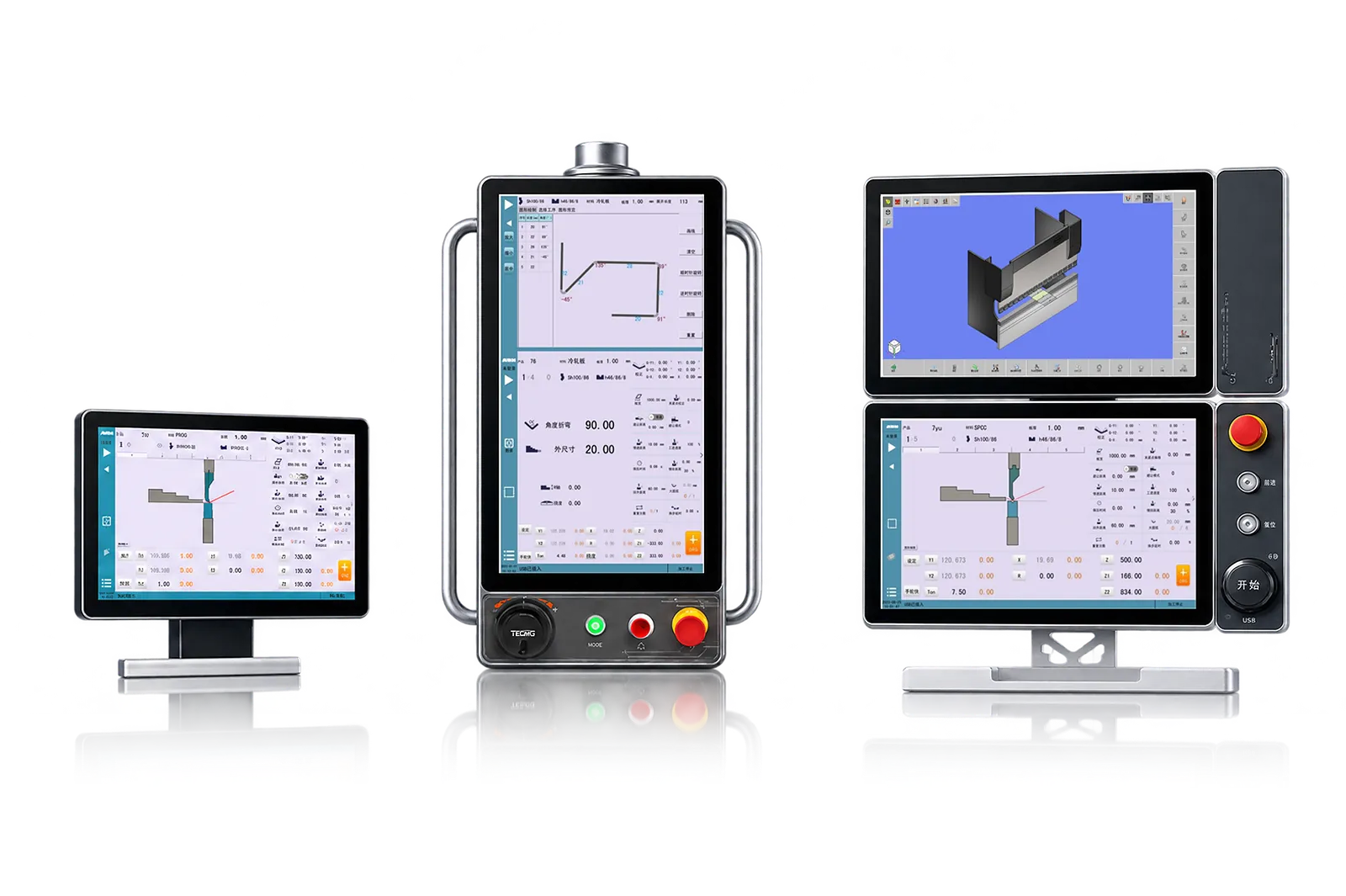
01
ACS930H, ACS930S and ACS990 are WADE controller options. The selected controller coordinates the bend program and supported axes, with different software and interface capabilities.
Compare part entry, program transfer, language and the operator display. Include offline tools and automation functions in the quotation when required.
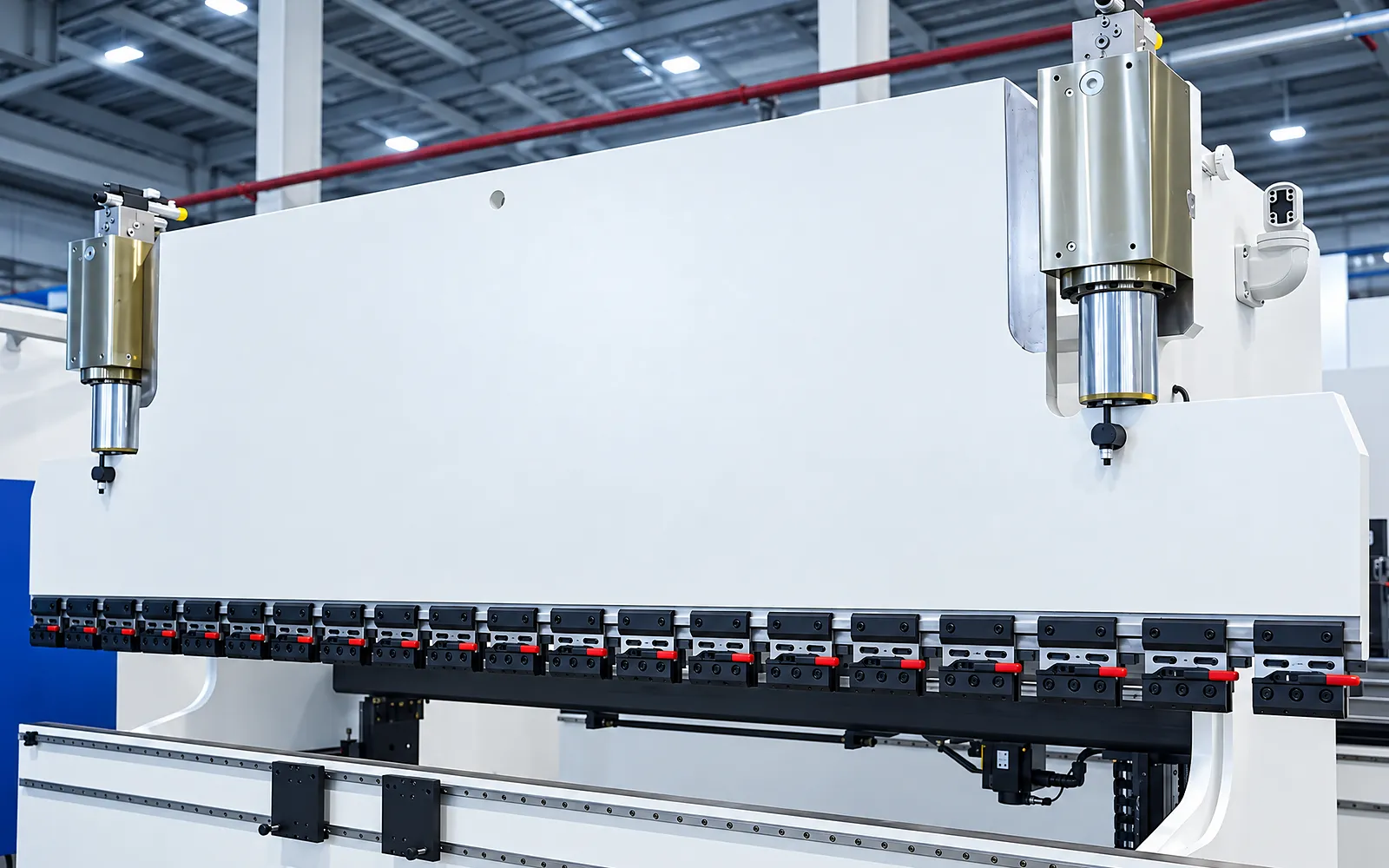
02
Independent cylinder control, position feedback and proportional hydraulic control coordinate the left and right ram positions with the programmed stroke.
Use the selected WADE model for motor, pump, stroke and speed data. A sample bend checks the combined effect of motion, material and tools.
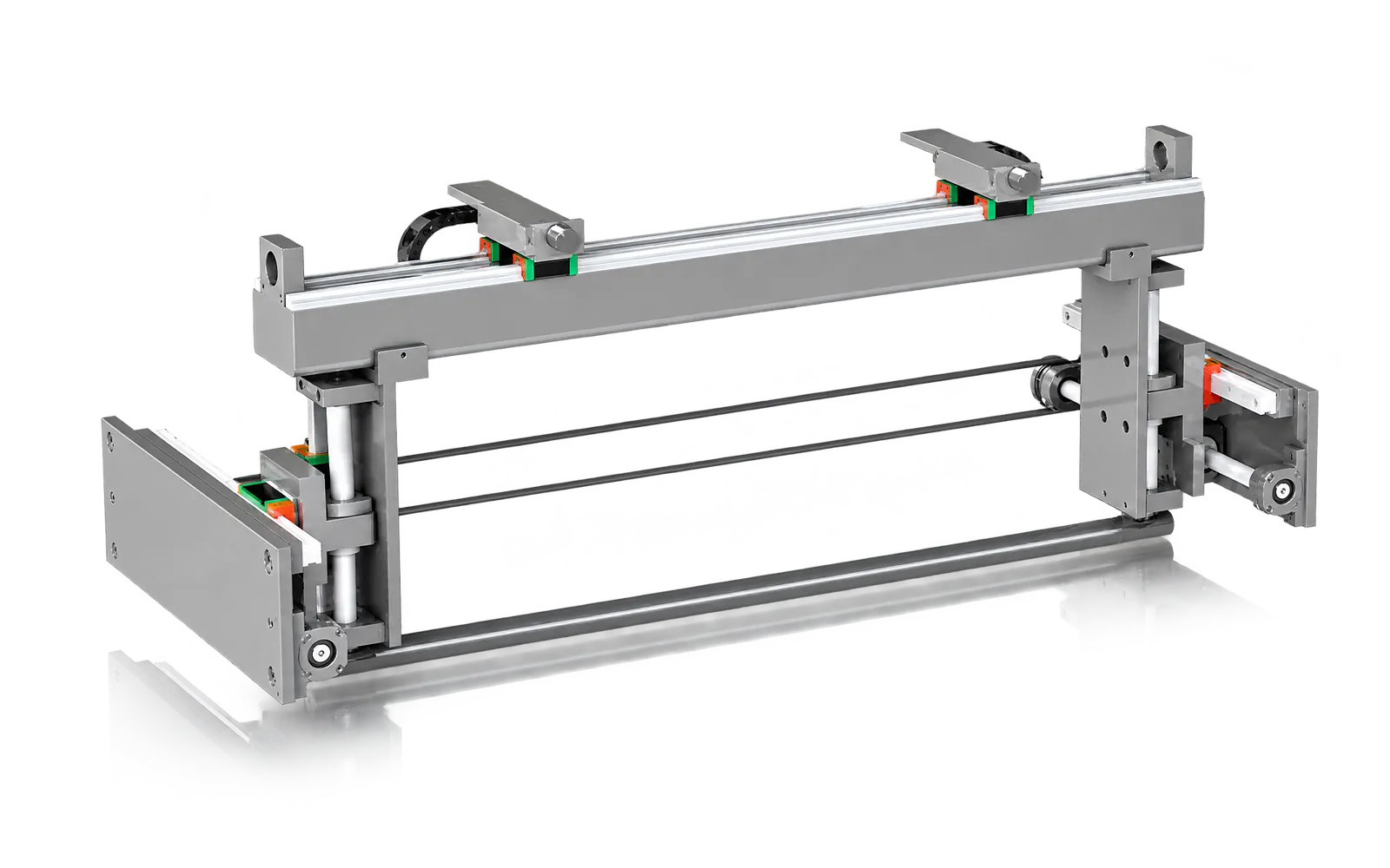
Backgauge
X and R positioning establish the backgauge distance and height for the bend.
Check flange access, travel and possible collisions through the complete sequence.
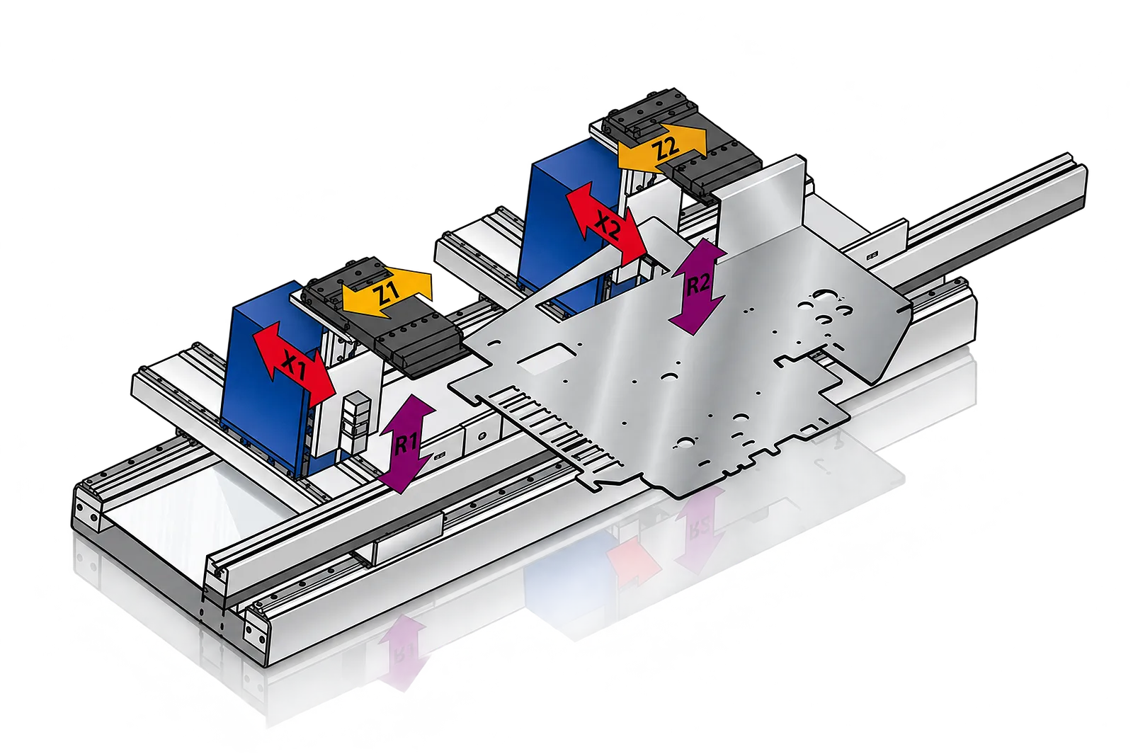
Axis expansion
Extra axes and different finger layouts can accommodate references that a simpler arrangement cannot conveniently reach.
Choose additional axes from the drawing and access requirements, rather than axis count alone.
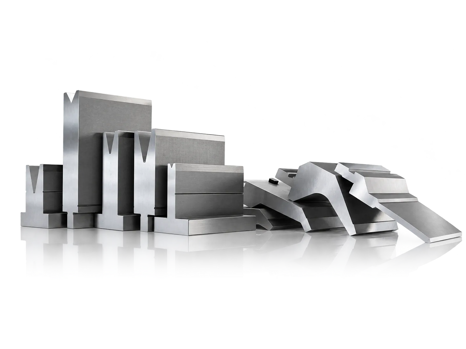
Tooling
Punch and die geometry and the lower-die interface establish the space in which the part is formed.
Review tool profile, die opening and line load against the part family.
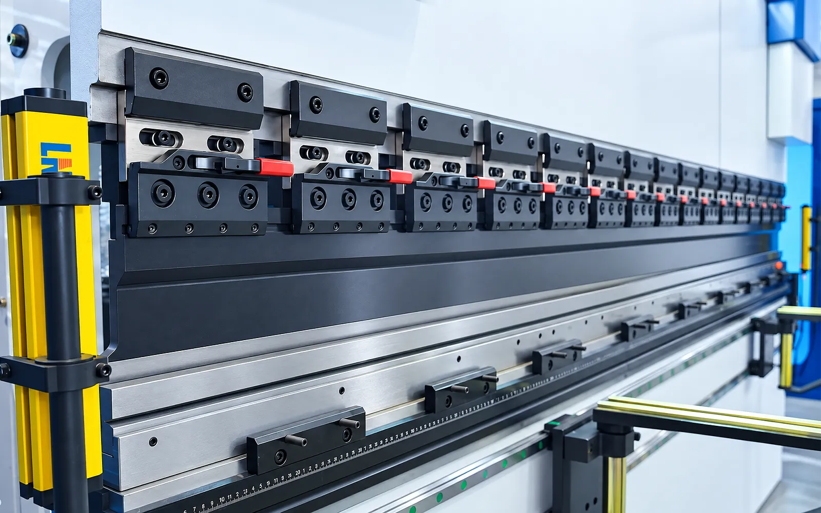
Clamp interfaces
Clamping holds the tooling in its working reference and determines how it is changed.
Check tool compatibility. Quick or pneumatic clamping and the supplied tool set depend on the ordered package.
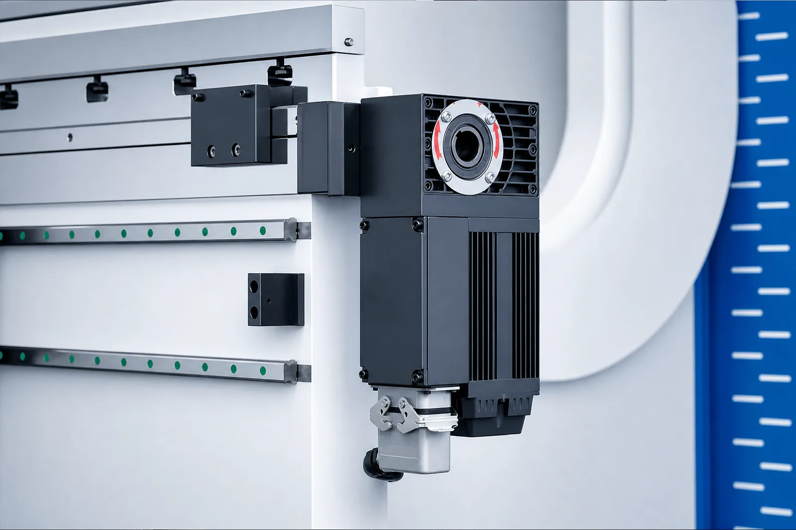
05
Crowning adjusts for deflection under bending load. The selected compensation system must work with the tooling and programmed ram positions across the required bend length.
Check the compensation arrangement and the angle-measurement method for long parts. Tool load capacity and part support remain part of the same selection.
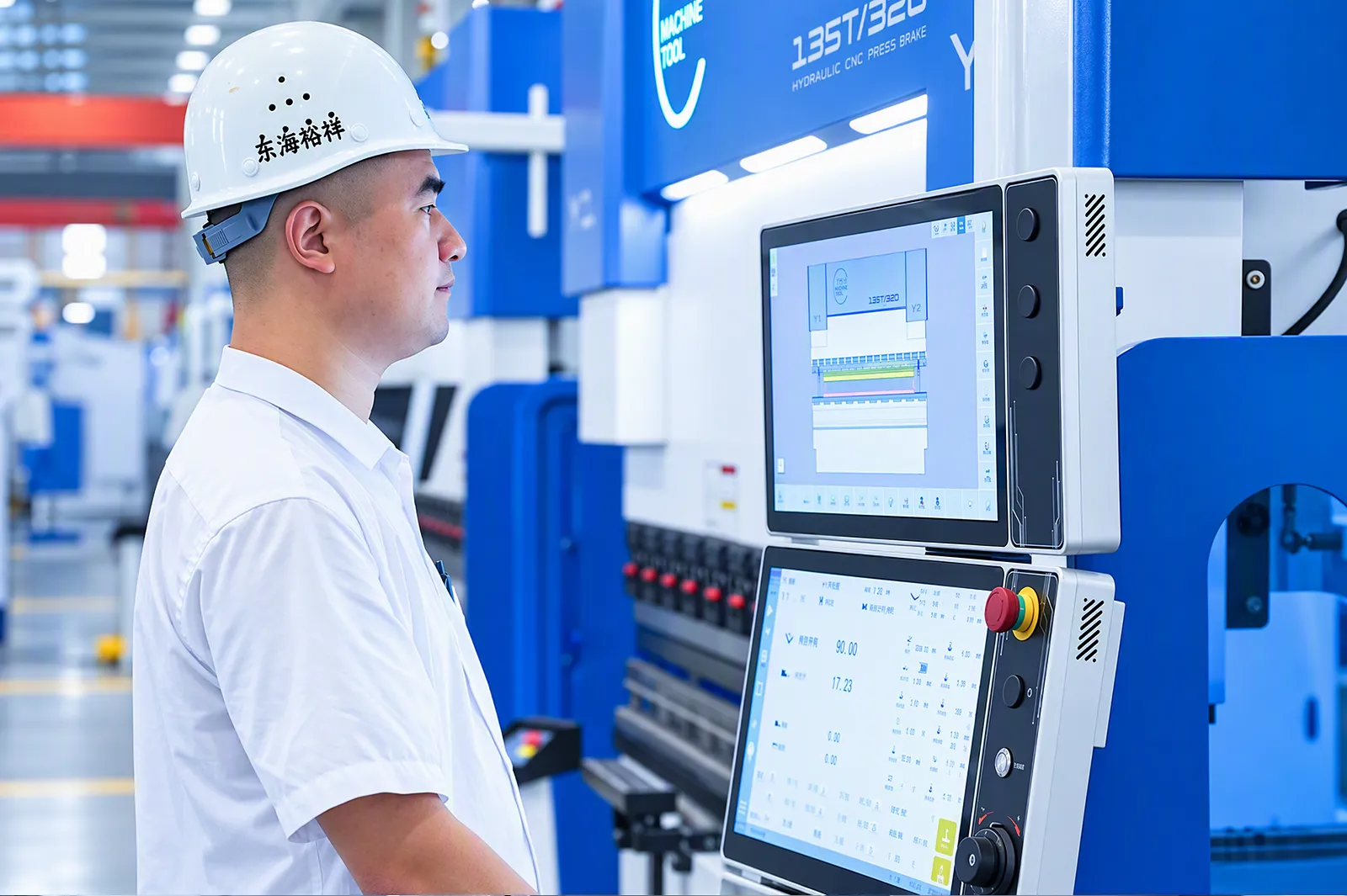
Part trial
Run a representative part through ACS programming, positioning and bending.
Agree the drawing, material and inspection points, then check the finished dimensions.
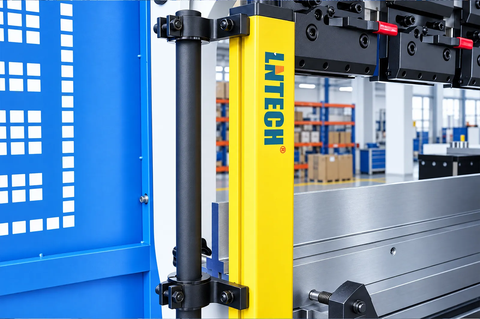
Safeguarding
Review operator access, part support and intervention points around the bending task.
Specify optical protection, foot controls, perimeter guarding and automation interfaces for the installation.
Series boundary
WAD and WADE have separate controllers, electrical specifications, dimensions, weights and model ranges.
The WADE table lists 25 models from 50T/1300 to 300T/6000 with model-specific motion, motor options, pump, opening and dimensions. Confirm the delivered configuration and machine weight in the quotation.
WAD has a separate 50T–300T table and controller configuration. Use WAD when that control and electrical package better fits the application.
View WAD SeriesFinalize force, tooling, controller, axes, motor, open height, stroke, throat, electrical supply, safety equipment and the sample acceptance test before order.
Related machines & selection
Through the machine lifecycle
Find the training, maintenance guidance and parts support your team needs. Services and availability are confirmed for your machine and location.
Before start-up
Prepare utilities, lifting and the installation area, then coordinate start-up and handover.
Review installation supportBefore production
Build the operator, programming and maintenance skills required for your delivered machine.
Explore trainingIn operation
Get support with the machine model, serial number and a clear description of the issue.
Request technical supportPlanned spares
Identify your machine and component so our team can check compatibility and availability.
Request service or partsSelf-service
Find video guidance for operating and maintaining your ADH machine. Check relevance to your model and configuration.
Browse support videosContract scope
Your quotation or contract defines included services, warranty, exclusions and responsibilities.
Review service scopeProject enquiry
Tell us what you want to make or improve. Technical details and drawings can follow.
Contact ADH
Name, email and a short description are enough to begin.