
01
Material and profile
Provide grade, plate thickness, angle/channel/bar/round sections and surface condition.
Ironworker
Configure the Q35Y hydraulic ironworker around your punching, plate and profile shearing, notching, tooling and workshop-handling requirements.
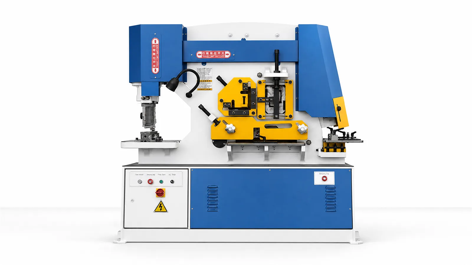
Technical specifications
Select one of the seven Q35Y models. The shearing data apply to material strength up to 450 N/mm². For Q35Y-50, the maximum shearing thickness is 12 mm. The thickness–width combination per stroke is awaiting engineering confirmation.
| Model | Q35Y-50 | Q35Y-60 | Q35Y-90 | Q35Y-120 | Q35Y-160 | Q35Y-200 | Q35Y-250 |
|---|---|---|---|---|---|---|---|
| Pressure (T) | 50 | 60 | 90 | 120 | 160 | 200 | 250 |
| Max. Shearing Thickness (mm) | 12 | 16 | 20 | 25 | 30 | 40 | 50 |
| Material Strength (N/mm²) | ≤450 | ≤450 | ≤450 | ≤450 | ≤450 | ≤450 | ≤450 |
| Shearing Angle (°) | 7° | 7° | 8° | 8° | 8° | 8° | 8° |
| Plate shear per stroke · pair A · thickness (mm) | Pending confirmation | 16 | 20 | 25 | 30 | 35 | 40 |
| Plate shear per stroke · pair A · width (mm) | Pending confirmation | 250 | 330 | 330 | 335 | 400 | 400 |
| Plate shear per stroke · pair B · thickness (mm) | Unconfirmed | 8 | 10 | 16 | 20 | 25 | 30 |
| Plate shear per stroke · pair B · width (mm) | Unconfirmed | 400 | 480 | 600 | 600 | 700 | 750 |
| Ram Stroke (mm) | 35 | 80 | 80 | 80 | 80 | 80 | 80 |
| Strokes per Minute | 10-18 | 9-25 | 12-28 | 12-28 | 12-28 | 10 | 10 |
| Throat Depth (mm) | 115 | 300 | 355 | 400 | 600 | 600 | 600 |
| Max. Punching Thickness (mm) | 12 | 16 | 20 | 25 | 28 | 35 | 40 |
| Max. Punching Diameter (mm) | 25 | 25 | 30 | 35 | 28 | 40 | 40 |
| Main Motor (KW) | 4 | 5.5 | 7.5 | 11 | 11/15 | 15/18.5 | 18.5/22 |
| Overall Dimensions (L x W x H) (mm) | 950×550×1800 | 1640×730×1770 | 1860×800×1900 | 2355×960×2090 | 2680×1040×2300 | 2970×1240×2350 | 3000×1440×2450 |
Application inputs
An ironworker is selected from the operations, profiles, tooling clearances and handling path—not from force alone.
01
Provide grade, plate thickness, angle/channel/bar/round sections and surface condition.
02
Identify punching, plate or profile shearing, angle cutting and notching tasks with hole geometry and tool clearances.
03
Share part lengths/weights, batch mix, feed/support method, station sequence and operator workflow.
04
Confirm destination power, access, safeguarding and the representative-part measurements for each required operation.
Machine in operation
Watch the Q35Y operating sequence, then compare each station, tooling and material-handling task with your parts.
Watch on YouTube (opens in a new tab)Product systems
Choose an ironworker by the operations you need to perform. Punching, angle cutting, bar cutting, notching and plate shearing each have their own tooling, clearance and capacity limits.
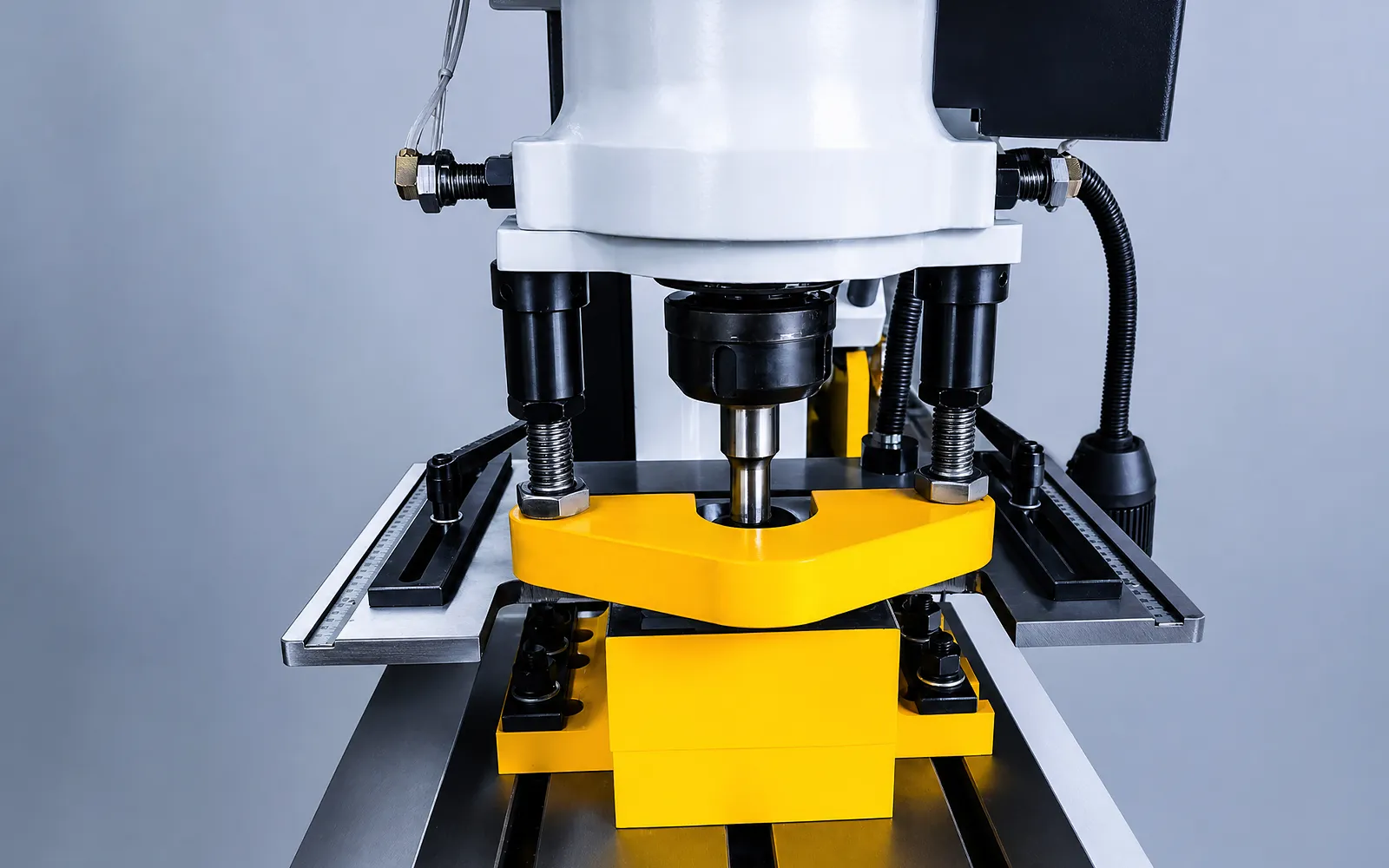
01
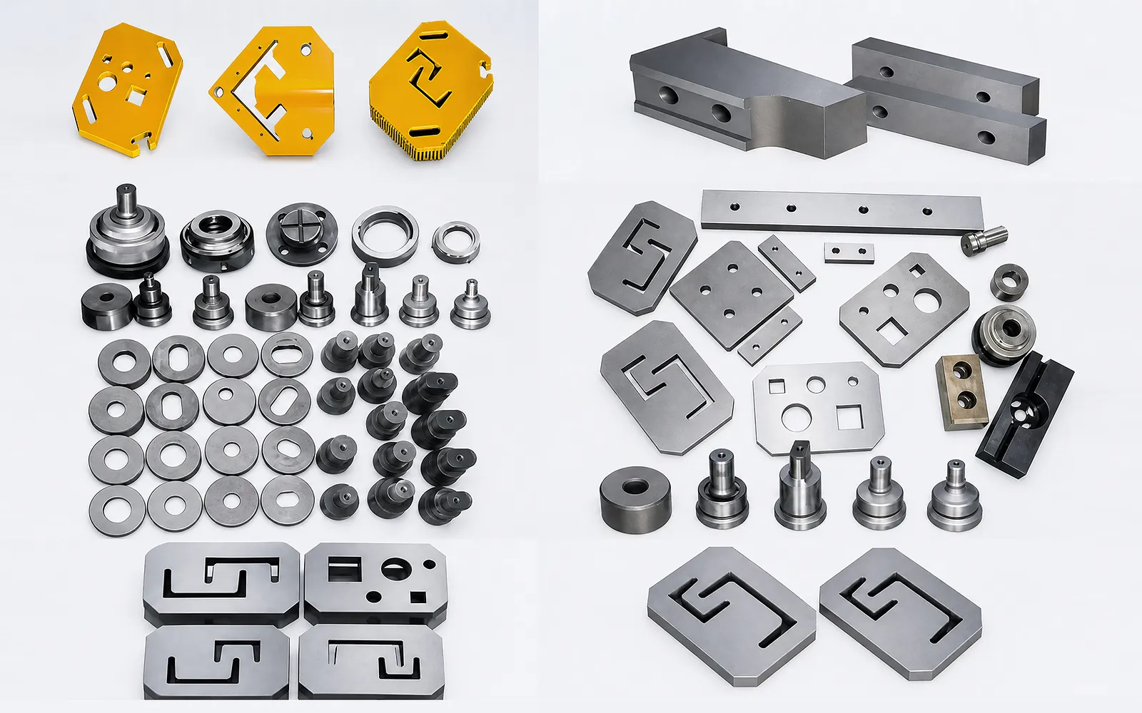
The punching station uses a matched punch and die to make the required hole. Tool shape, throat depth and access determine which workpieces can be positioned.
Check the hole size, material thickness and station capacity together. Specify the required punch and die set for the chosen Q35Y model.
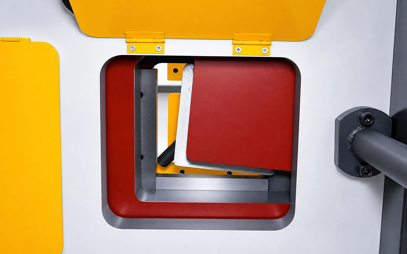
02
The angle-cutting station cuts angle stock with its designated blade arrangement. Workpiece access and the blade set determine how the section sits at the cut.
Use the selected model for section capacity. Evaluate the required cut face and dimensional result on the intended material.
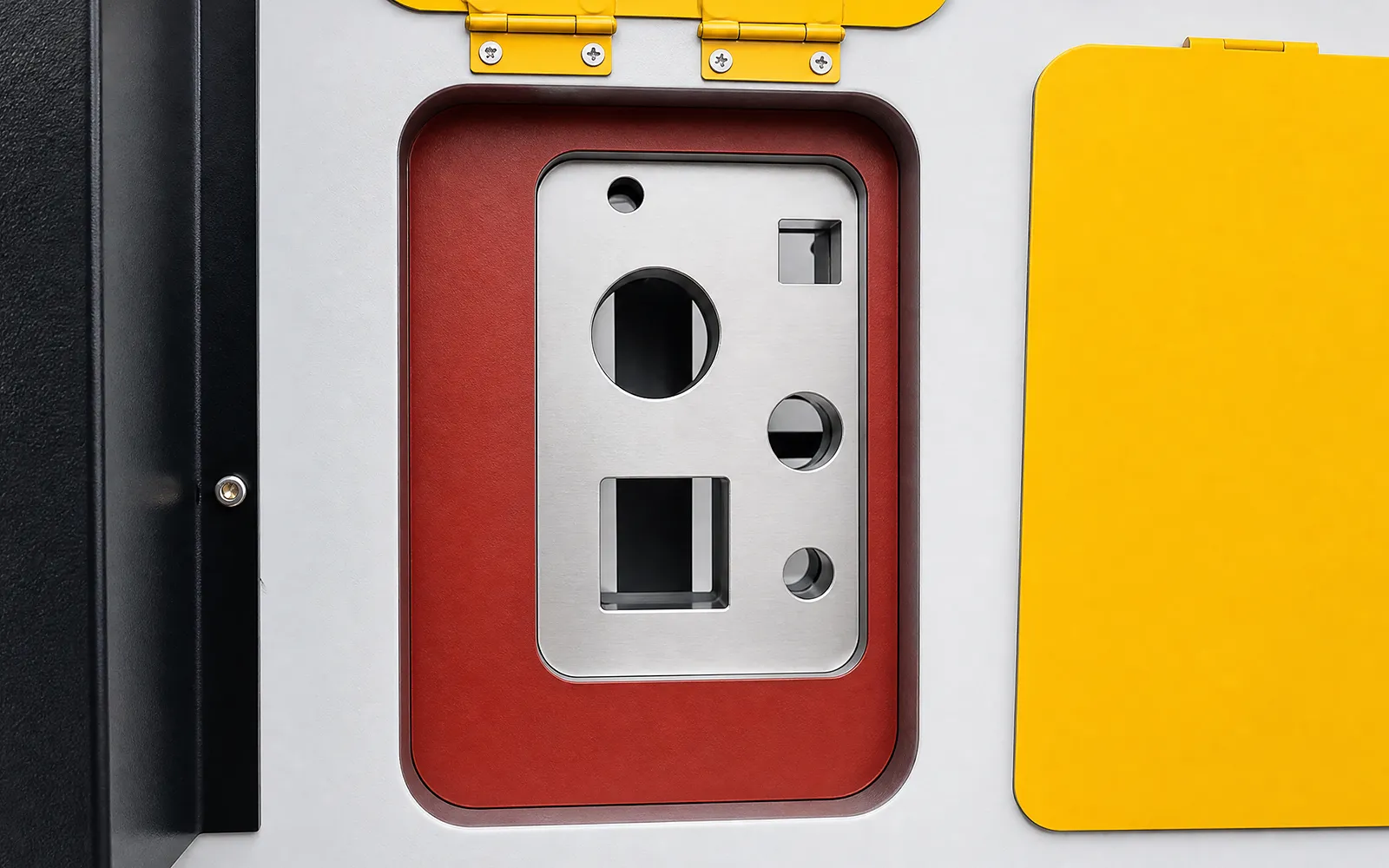
03
For round bar, square bar, angle or channel, specify the section dimensions, cut angle and material grade. ADH can check these against the selected machine and blade set.
Confirm the blade set, section dimensions and material. A capacity stated for one shape should not be applied to another.
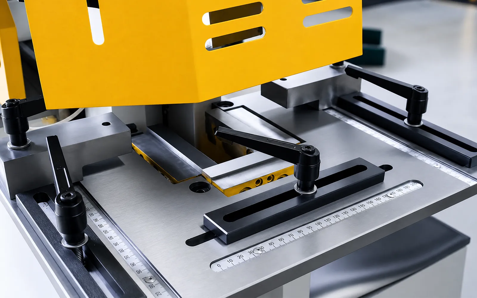
04
The notching station removes material with a dedicated tool set. The notch shape and available access determine whether the workpiece can be located correctly.
Compare the required geometry, stock thickness and finished-cut requirement with the selected station and tooling.
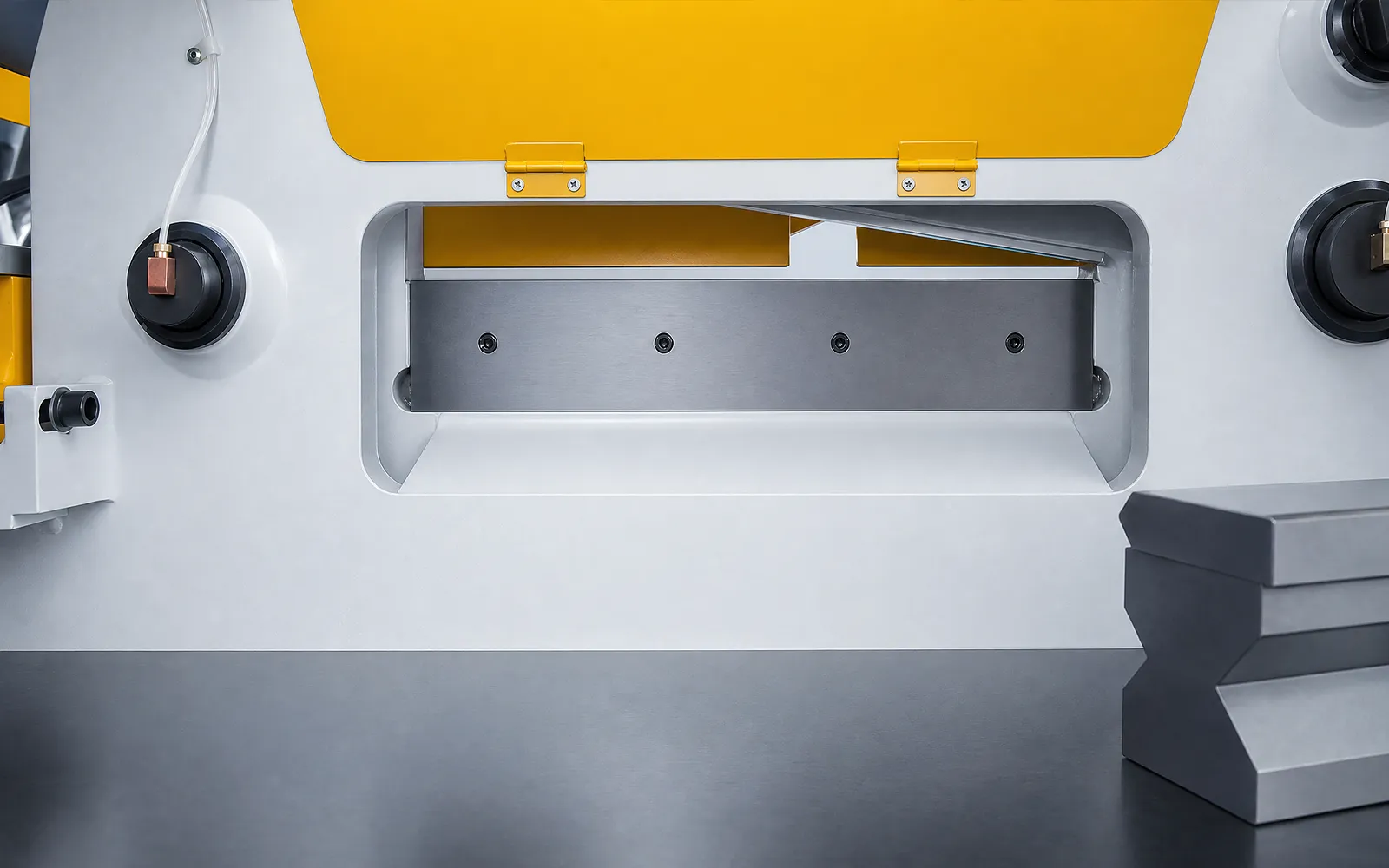
05
The shearing station separates plate between its blades. Thickness, cut width, blade clearance and support all affect the usable task.
Read the station-specific capacity for the intended material. Check how the plate and offcut will be supported and removed.
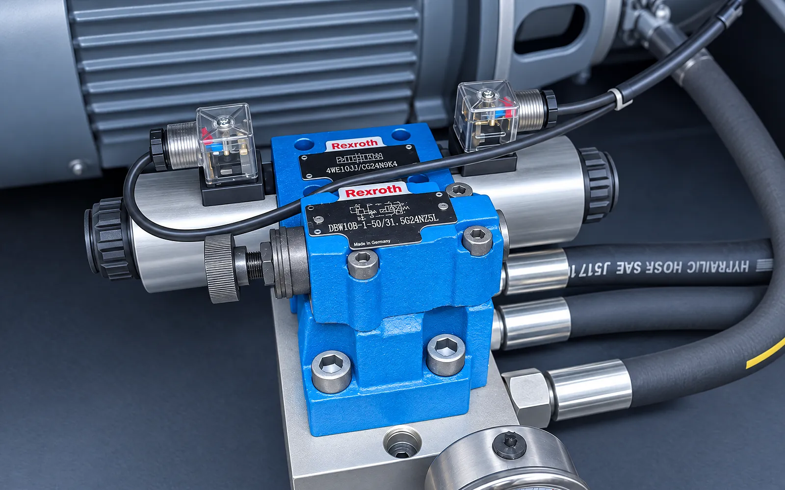
Hydraulics
The hydraulic circuit supplies force to the selected punching, cutting or notching station.
Review the selected model and its station-specific operating requirements.
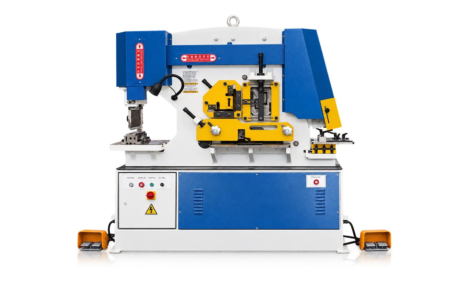
Stock handling
Long bar, angle and plate need practical feed, support and offcut routes.
Check stock dimensions against station clearances, operating controls and guarding. Identify the required handling equipment.
07
A useful trial covers the actual punching, cutting or notching tasks in your workload. Inspect hole positions, cut dimensions and finish as applicable.
Use the agreed tools, material and drawing. Assess each operation against its own Q35Y station limit and inspection criteria.
Configuration boundary
Use the selected Q35Y model for punch, plate-shear and throat dimensions. For profile shearing or notching, include a section drawing and the required cut so the station and tooling can be confirmed.
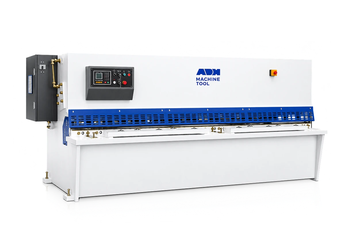
Compare Q35Y-50 through Q35Y-250 models by the capacity of each required station.
Punch, shear, angle/notch tooling, hydraulic/control details and safeguards follow the selected model and quotation.
Run the agreed material and operations, then record dimensions, edge/cut quality, sequence and handoff checks.
Related machines & selection
Through the machine lifecycle
Find the training, maintenance guidance and parts support your team needs. Services and availability are confirmed for your machine and location.
Before start-up
Prepare utilities, lifting and the installation area, then coordinate start-up and handover.
Review installation supportBefore production
Build the operator, programming and maintenance skills required for your delivered machine.
Explore trainingIn operation
Get support with the machine model, serial number and a clear description of the issue.
Request technical supportPlanned spares
Identify your machine and component so our team can check compatibility and availability.
Request service or partsSelf-service
Find video guidance for operating and maintaining your ADH machine. Check relevance to your model and configuration.
Browse support videosContract scope
Your quotation or contract defines included services, warranty, exclusions and responsibilities.
Review service scopeProject enquiry
Tell us what you want to make or improve. Technical details and drawings can follow.
Contact ADH
Name, email and a short description are enough to begin.