
01
Plate envelope
Provide length, width, thickness, weight, flatness, material and loading/removal route.
Large-Format Laser Cutting | ULG Series
A ground-rail platform for long and heavy plate work, with rails, supports, extraction and handling engineered around the workpiece and site.
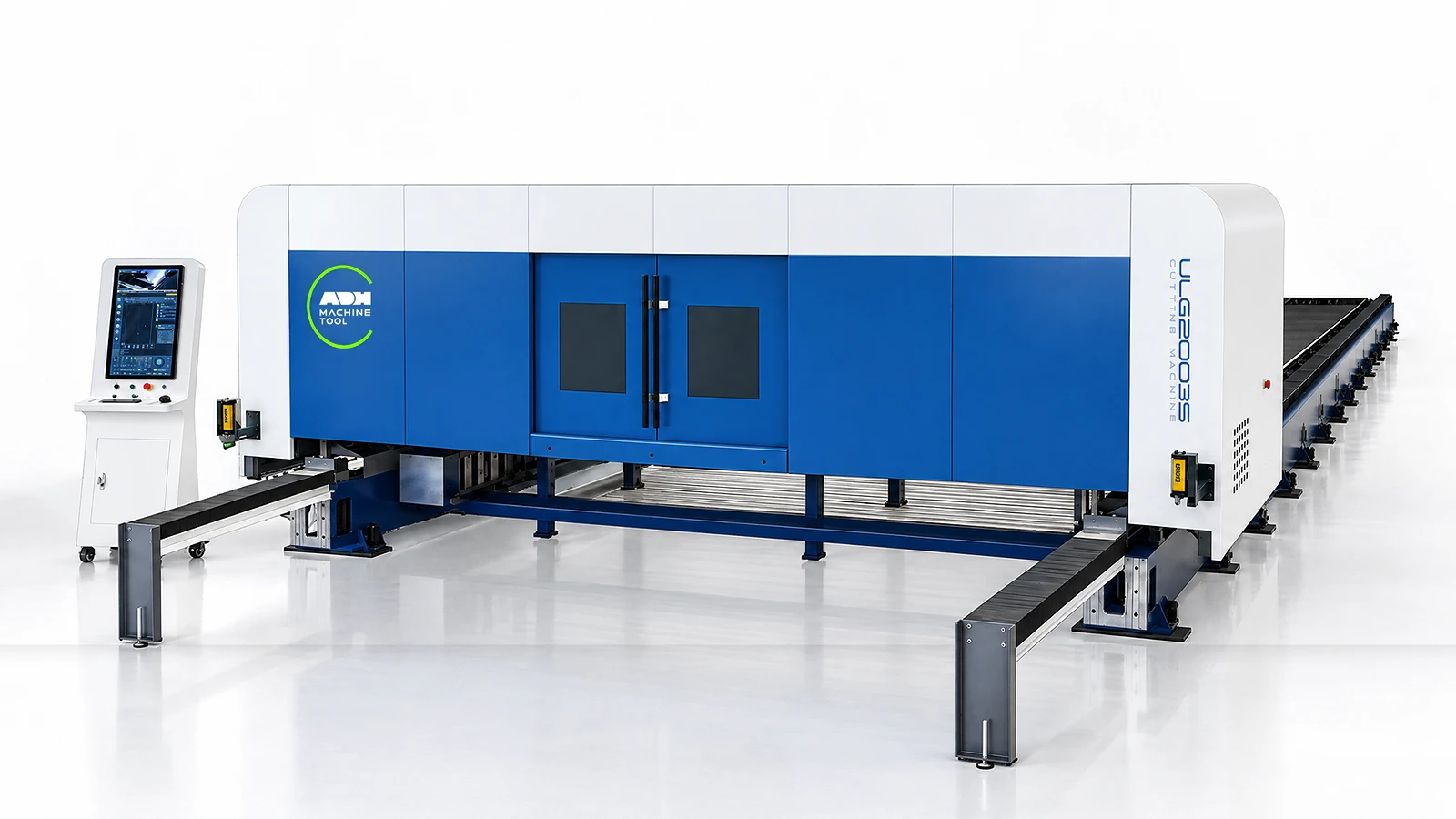
Technical specifications
Select one ULG-A or ULG-C model. Motion, load and dimensions are model-specific. For ULG-C within the listed 12–60 kW range, beam clearance is 190 mm up to 40 kW and 300 mm at 60 kW.
| Model | Family | Laser Power | Processing Area | Z Travel | Beam Clearance | Positioning Accuracy | Repeatability | Max Coupled Speed | Max Coupled Acceleration | Table Load | Overall Dimensions | Rated Voltage | Frequency |
|---|---|---|---|---|---|---|---|---|---|---|---|---|---|
| Unit | kW | mm | mm | mm | mm/m | mm | m/min | g | kg | mm | V | Hz | |
| ULG13035C | ULG-C | 12–60 | 13000×3500 | 250 | 190 (≤40 kW); 300 (60 kW) | ≤±0.03 | X axis ≤±0.03; Y axis ≤±0.05 | 70 | 0.8 | 35700 | 16450×5400×2200 | 380 | 50 |
| ULG13040C | ULG-C | 12–60 | 13000×4000 | 250 | 190 (≤40 kW); 300 (60 kW) | ≤±0.03 | X axis ≤±0.03; Y axis ≤±0.05 | 60 | 0.7 | 40800 | 16450×5900×2200 | 380 | 50 |
| ULG13045C | ULG-C | 12–60 | 13000×4500 | 250 | 190 (≤40 kW); 300 (60 kW) | ≤±0.03 | X axis ≤±0.03; Y axis ≤±0.05 | 50 | 0.6 | 45900 | 16450×6390×2200 | 380 | 50 |
| ULG26035C | ULG-C | 12–60 | 26000×3500 | 250 | 190 (≤40 kW); 300 (60 kW) | ≤±0.03 | X axis ≤±0.03; Y axis ≤±0.07 | 70 | 0.8 | 71400 | 30700×5390×2200 | 380 | 50 |
| ULG26040C | ULG-C | 12–60 | 26000×4000 | 250 | 190 (≤40 kW); 300 (60 kW) | ≤±0.03 | X axis ≤±0.03; Y axis ≤±0.07 | 60 | 0.7 | 81600 | 31100×5890×2200 | 380 | 50 |
| ULG26045C | ULG-C | 12–60 | 26000×4500 | 250 | 190 (≤40 kW); 300 (60 kW) | ≤±0.03 | X axis ≤±0.03; Y axis ≤±0.07 | 50 | 0.6 | 91800 | 31100×6390×2200 | 380 | 50 |
| ULG13035A | ULG-A | 12–60 | 13000×3500 | 250 | 190 | ≤±0.03 | X axis ≤±0.03; Y axis ≤±0.04 | 80 | 1.1 | 35700 | 16200×5300×1950 | 380 | 50 |
| ULG13040A | ULG-A | 12–60 | 13000×4000 | 250 | 190 | ≤±0.03 | X axis ≤±0.03; Y axis ≤±0.04 | 70 | 1 | 40800 | 16200×5800×1950 | 380 | 50 |
| ULG13045A | ULG-A | 12–60 | 13000×4500 | 250 | 190 | ≤±0.03 | X axis ≤±0.03; Y axis ≤±0.04 | 60 | 0.85 | 45900 | 16200×6300×1950 | 380 | 50 |
| ULG26035A | ULG-A | 12–60 | 26000×3500 | 250 | 190 | ≤±0.03 | X axis ≤±0.03; Y axis ≤±0.06 | 80 | 1.1 | 71400 | 30500×5300×1950 | 380 | 50 |
| ULG26040A | ULG-A | 12–60 | 26000×4000 | 250 | 190 | ≤±0.03 | X axis ≤±0.03; Y axis ≤±0.06 | 70 | 1 | 81600 | 31100×5800×1950 | 380 | 50 |
| ULG26045A | ULG-A | 12–60 | 26000×4500 | 250 | 190 | ≤±0.03 | X axis ≤±0.03; Y axis ≤±0.06 | 60 | 0.85 | 91800 | 31100×6300×1950 | 380 | 50 |
Large-format inputs
Plate envelope, power, foundation, crane access, extraction and the acceptance sample must be defined together.
01
Provide length, width, thickness, weight, flatness, material and loading/removal route.
02
Define power, gas, edge and bevel criteria, minimum features and representative sample.
03
Compare a large-format ULF table with a ULG rail installation using the same plate, loaded weight and crane route. For the rail layout, confirm foundation alignment, support spacing, extraction zones and clearance for removing parts.
04
Record extraction zones, cooling, nesting, edge finding, remnants and data interfaces.
Machine in operation
Watch the ULG ground-rail sequence, then compare rails, supports, motion and process control below.
Watch on YouTube (opens in a new tab)Product systems
ULG-C separates the motion rails from the plate-support load path. Large-format cutting therefore needs the machine, foundation, handling and extraction to be planned together.
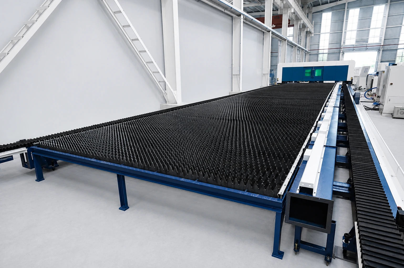
Rails
The ground rails carry the moving system across the selected working format.
Define alignment and commissioning responsibilities for the installed rail route.
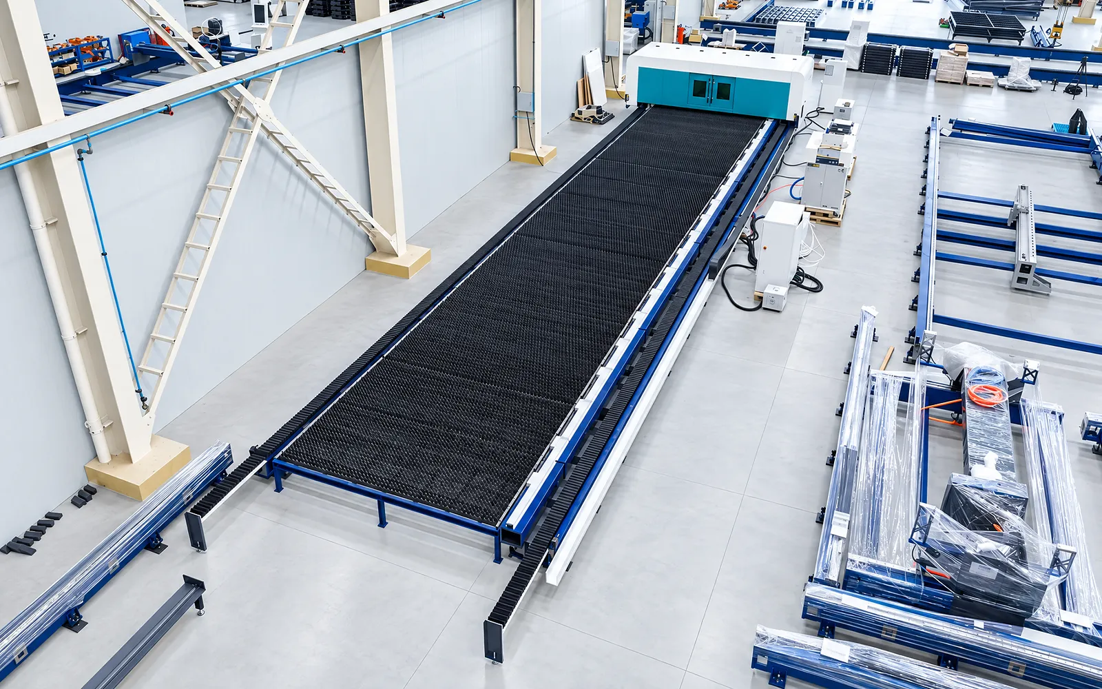
Foundation
The foundation forms part of the installation supporting the machine and stock load.
Agree civil-work responsibilities and installation requirements for the chosen format.
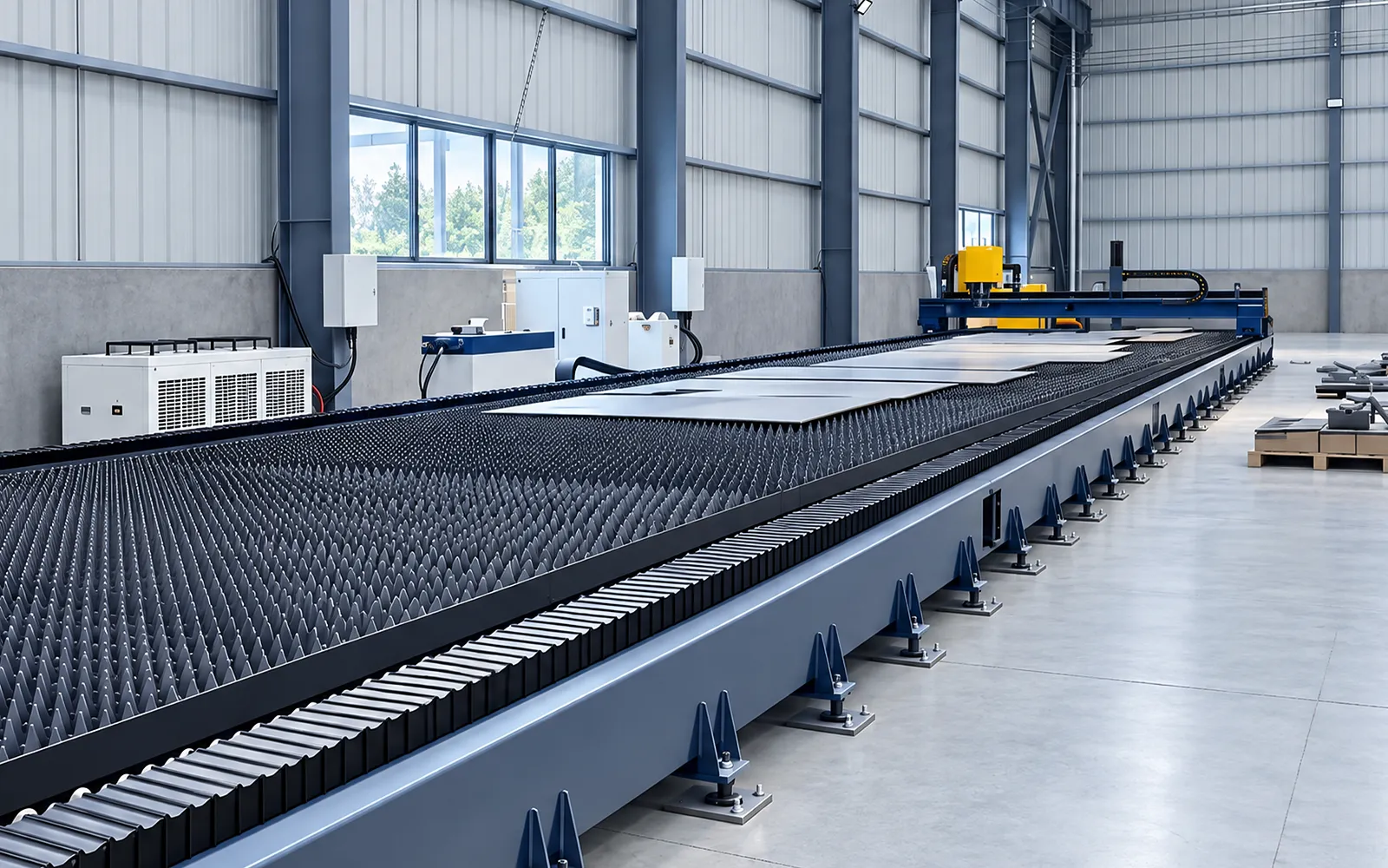
Plate support
Plate supports carry the stock within the working area.
Confirm support geometry and usable working area for the configured machine and installation.
02
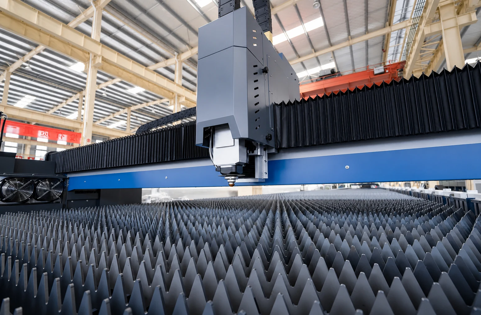
The gantry travels along the ground rails to position the cutting head. Transmission protection and lubrication support the long travel route.
The 13 m and 26 m routes have different width, speed, acceleration and drive data. Read the exact ULG-C configuration for the intended plate size.
Laser source
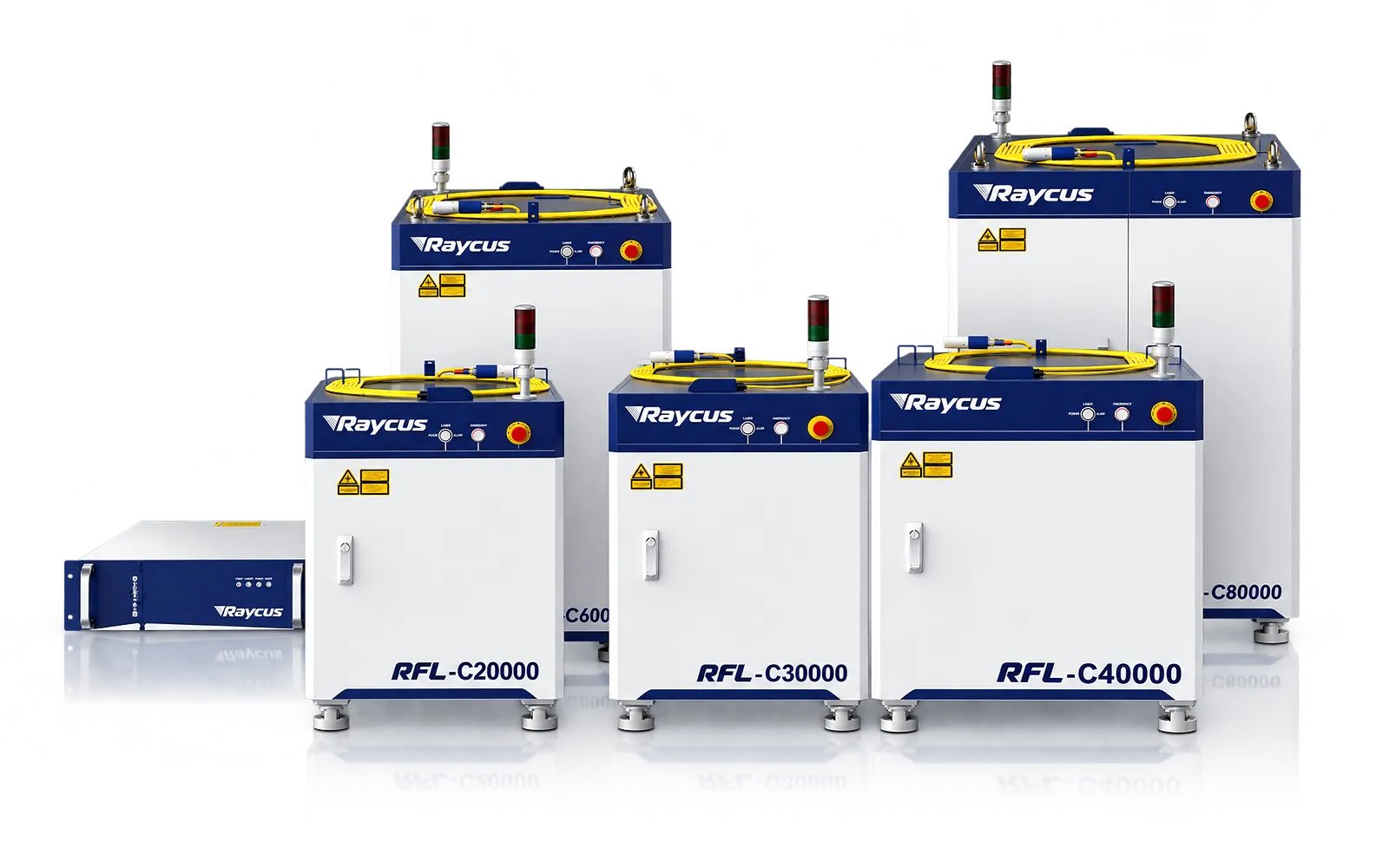
Laser power is selected around the material, thickness and required process.
Review the selected source with material samples; power alone does not establish edge quality.
Cutting-head package
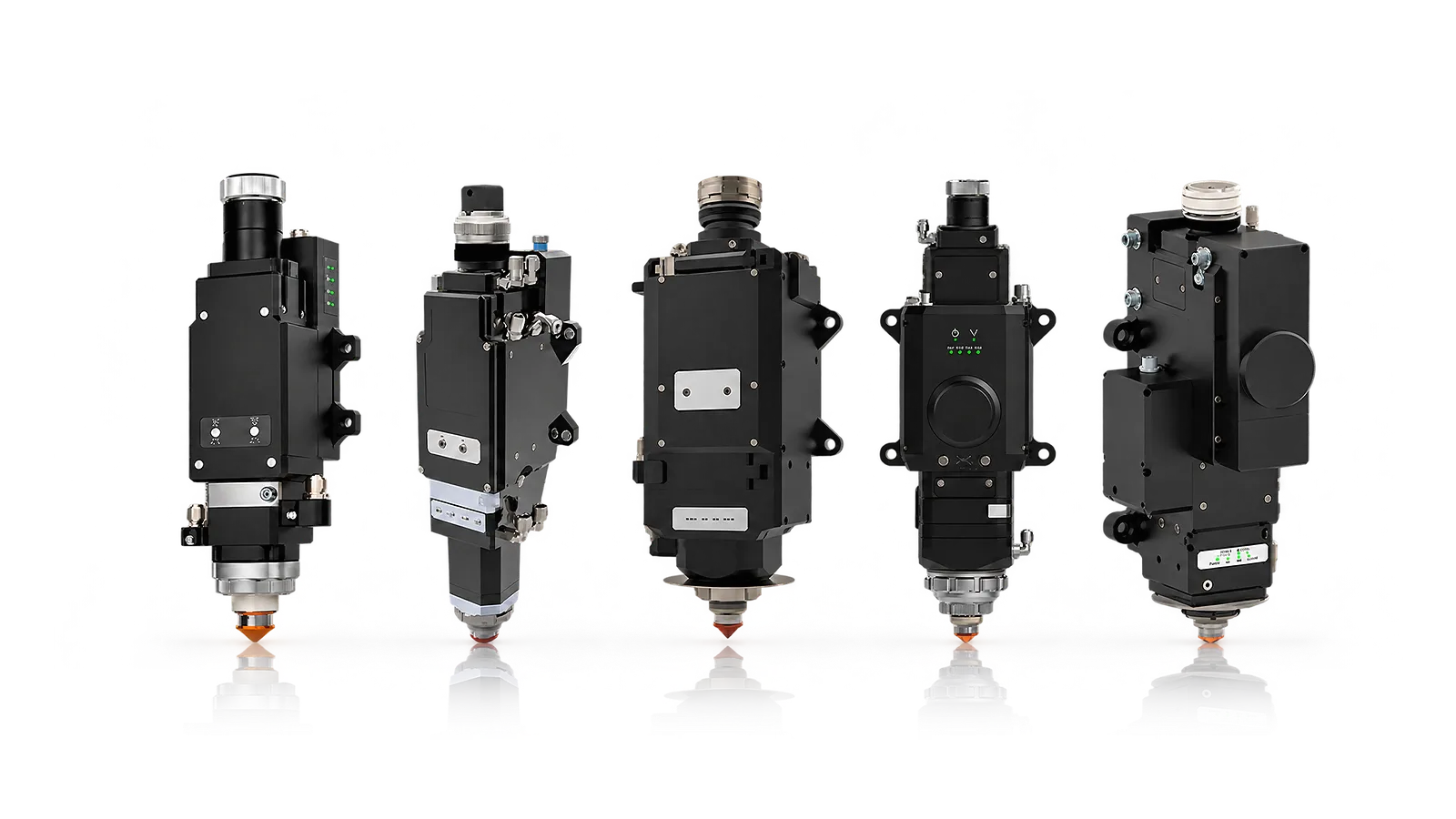
The cutting head works with assist gas and cooling over the configured working area.
Confirm head functions and utilities for the order and assess the required cut quality.
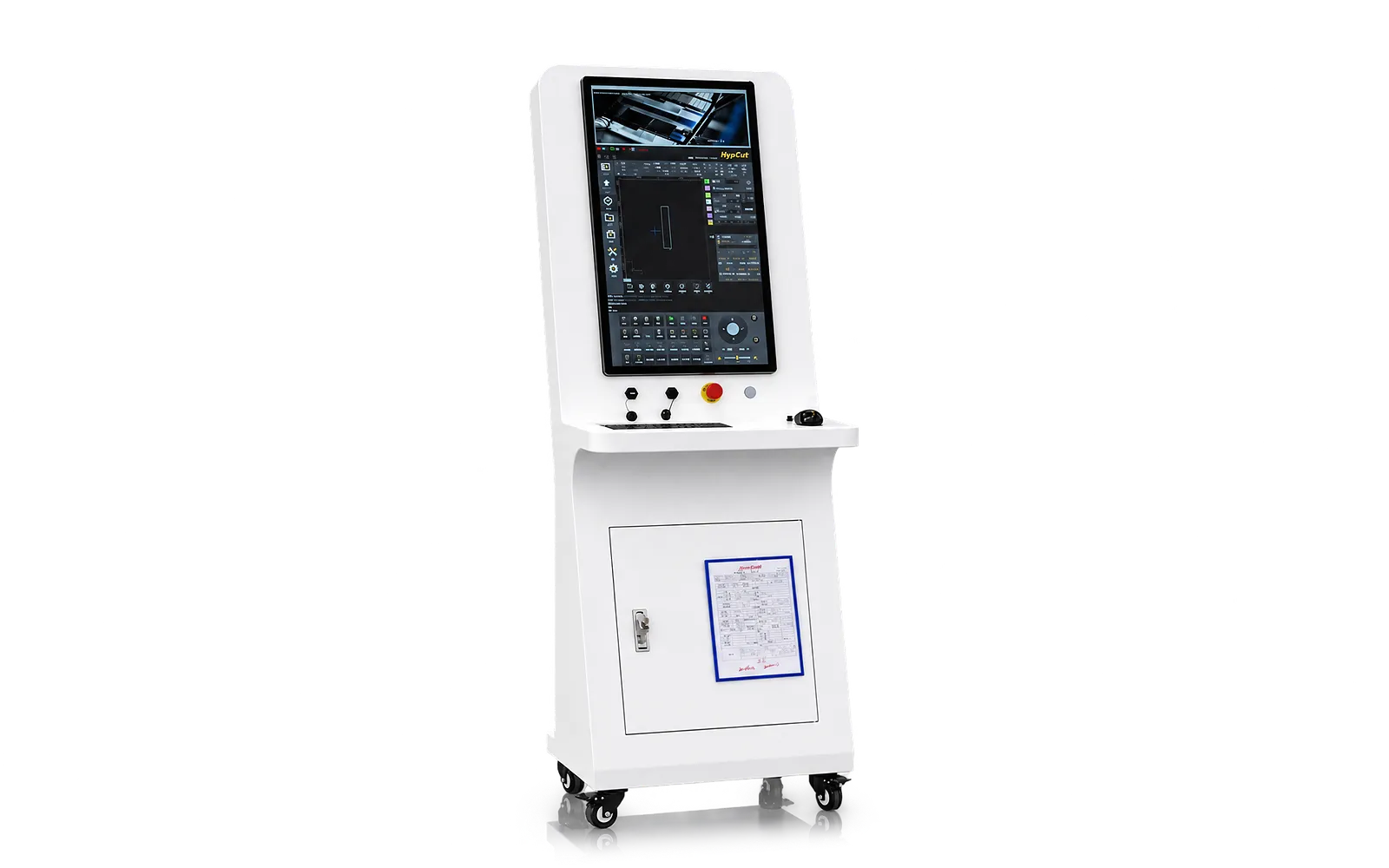
Plate programming
Edge finding, nesting, common-line and remnant functions support plate planning within the delivered software.
Match program preparation to the installed format and define transfer and recovery needs.
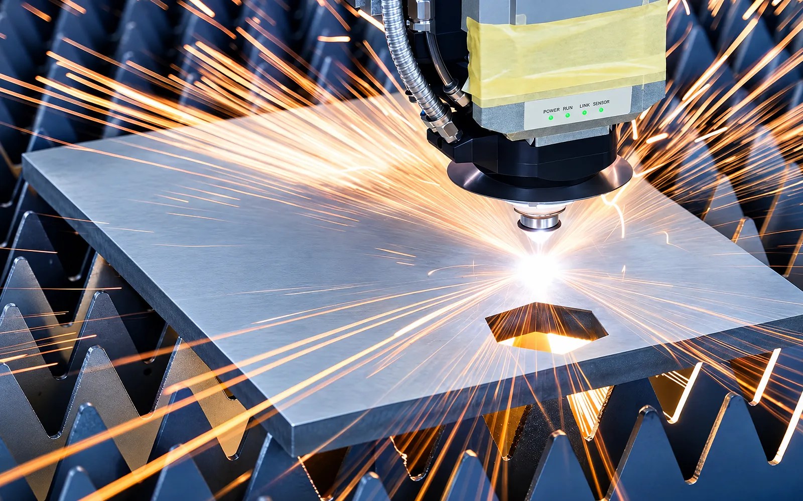
Optional functions
Bevel functions, industry file interfaces and MES connections require the corresponding configuration.
Define the required functions and integration scope before finalizing the package.
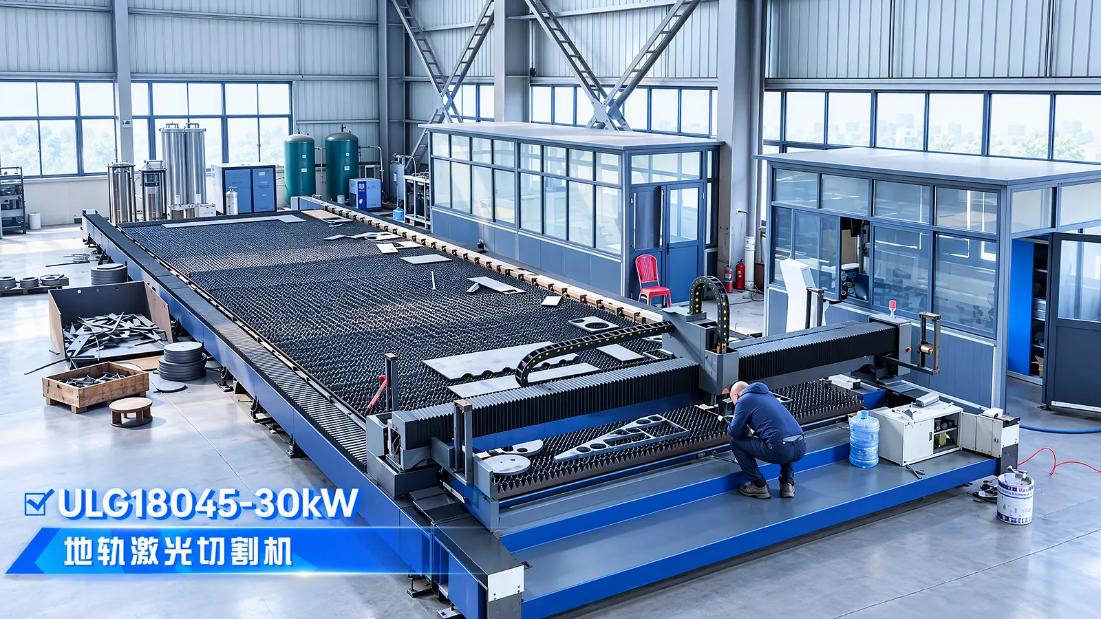
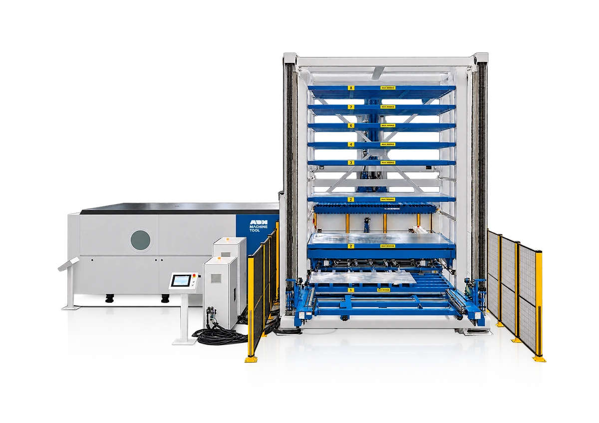
Lifting
Lifting access and support determine how the intended plate is placed in the working area.
Plan stock weight and access equipment around the installation.
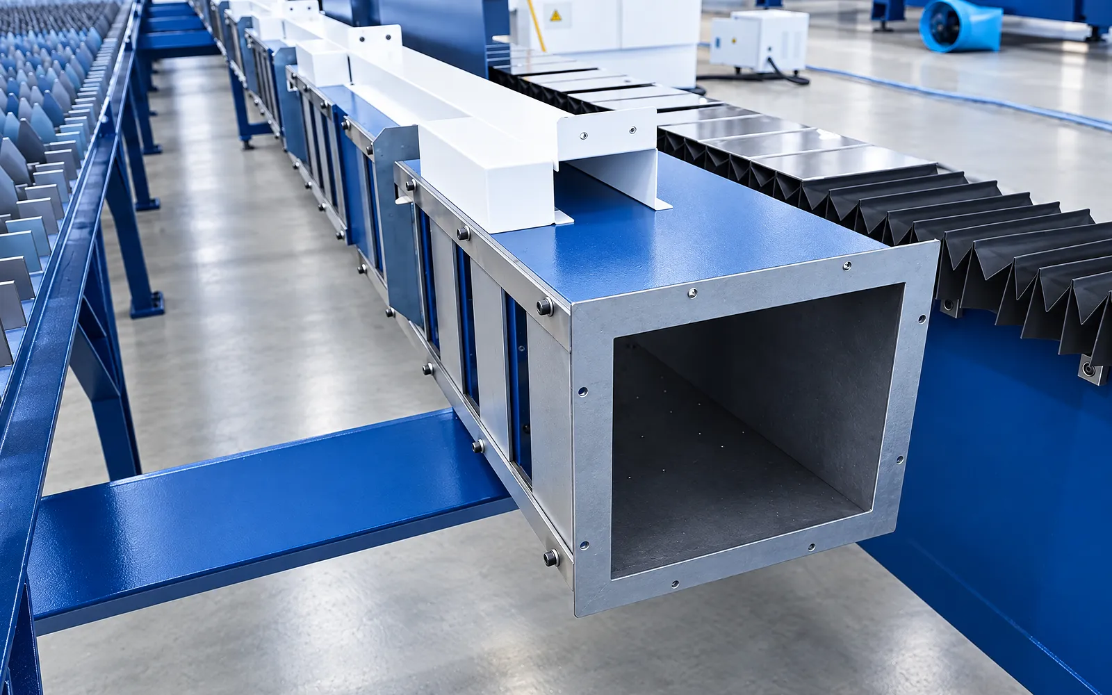
Extraction
The extraction arrangement must serve the active cutting zones and operating duty.
Specify the supplied equipment, site connections and required service access.
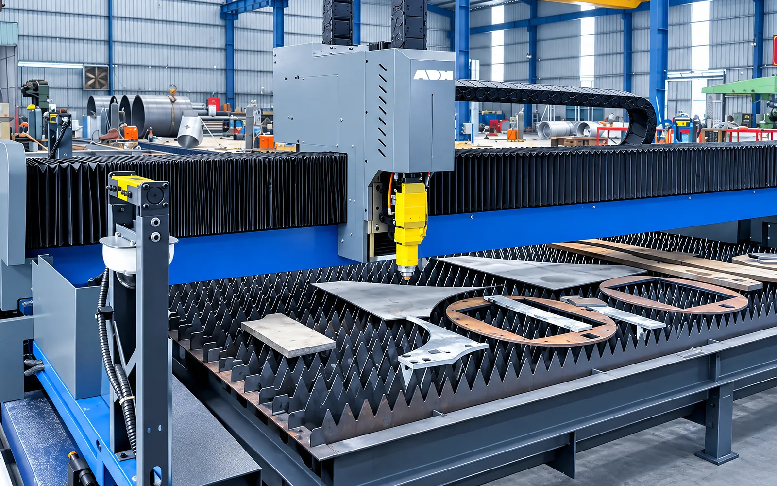
Material flow
Finished parts, remaining plate and process waste need practical routes out of the work area.
Coordinate removal and service clearances with the lifting and support layout.
06
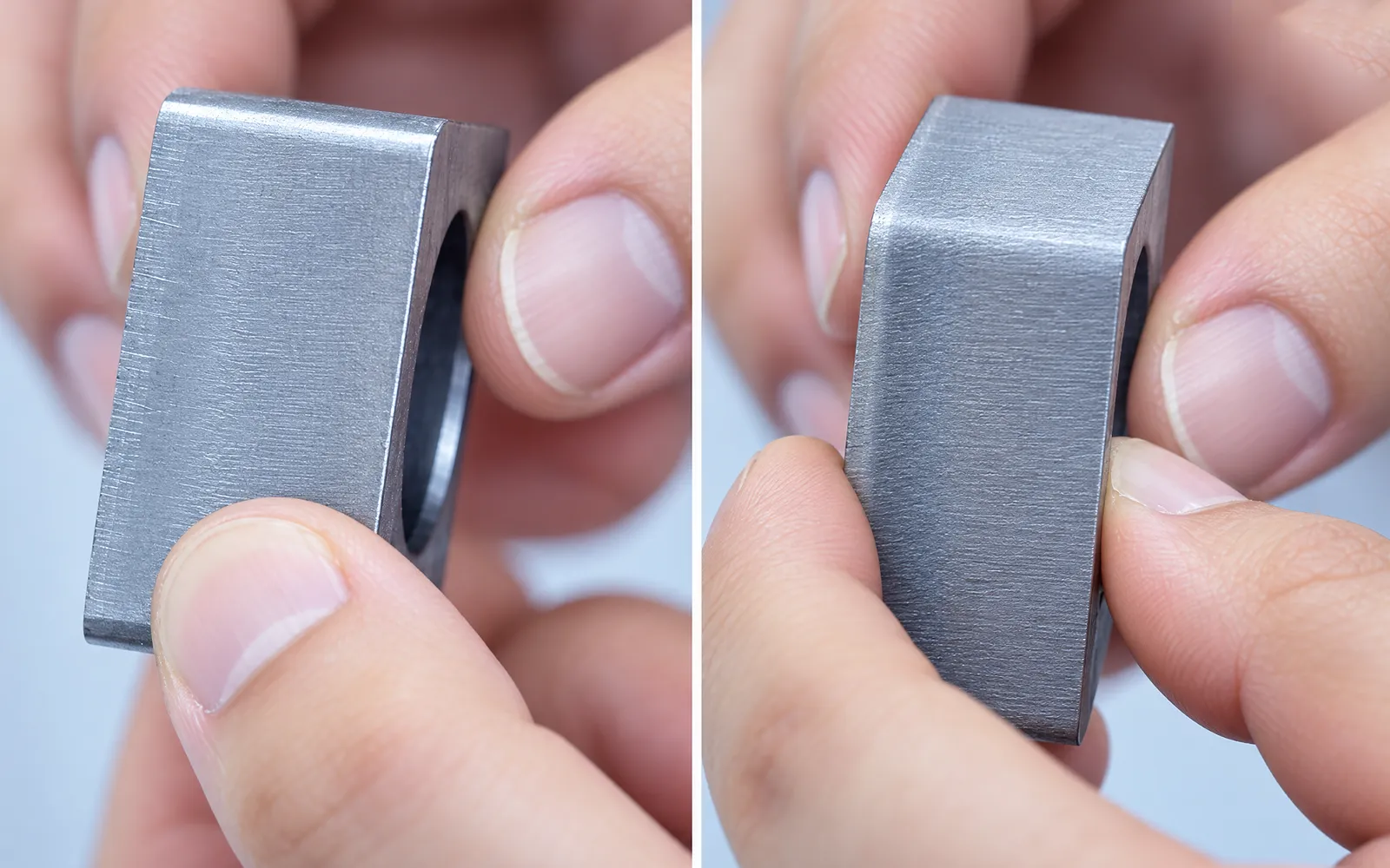
A representative trial checks alignment and cut quality at agreed positions across the working area. Use the intended material, gas and cutting program.
Record the installed configuration, survey conditions and inspection method. Include the handling route when reviewing the complete production task.
Model and site selection
Choose from ULG13035C–ULG26045C models, with working area and load limits specified for each configuration.
Use the exact ULG-C column for format, power compatibility, travel, precision, speed, acceleration, drive data, load, dimensions and mass.
Confirm included and optional bevel cutting, extraction, gas equipment, nesting, data integration and material handling.
Confirm foundation, rails, load, handling, sample, utilities, maintenance and safety.
Related machines & selection
Explore three ULG installations in China, with different heavy-plate parts, working formats and following operations.
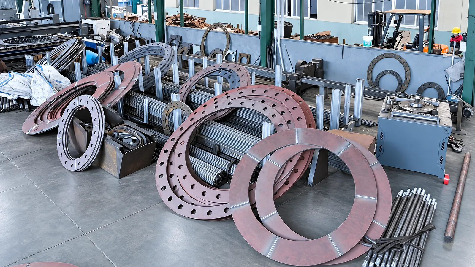
Tower components · Zhejiang, China
Moving tower baseplates and flanges from flame cutting and separate drilling to a combined laser-cutting operation.
Read Feiyue Hardware caseMining equipment · Zhejiang, China
An 18-metre, 30 kW ground-rail laser changed the route from heavy-plate cutting to welding and assembly.
Read Zhekuang Heavy Industry case
Heavy machinery · Zhejiang, China
A 20 kW ground-rail installation and joint technical support helped a heavy-equipment workshop shorten its reported production cycle.
Read Xingqiu Machinery caseThrough the machine lifecycle
Find the training, maintenance guidance and parts support your team needs. Services and availability are confirmed for your machine and location.
Before start-up
Prepare utilities, lifting and the installation area, then coordinate start-up and handover.
Review installation supportBefore production
Build the operator, programming and maintenance skills required for your delivered machine.
Explore trainingIn operation
Get support with the machine model, serial number and a clear description of the issue.
Request technical supportPlanned spares
Identify your machine and component so our team can check compatibility and availability.
Request service or partsSelf-service
Find video guidance for operating and maintaining your ADH machine. Check relevance to your model and configuration.
Browse support videosContract scope
Your quotation or contract defines included services, warranty, exclusions and responsibilities.
Review service scopeSee equipment options for the parts your industry produces.
Project enquiry
Tell us what you want to make or improve. Technical details and drawings can follow.
Contact ADH
Name, email and a short description are enough to begin.