01
Sheet work
Provide format, material, thickness, load, gas and edge result.
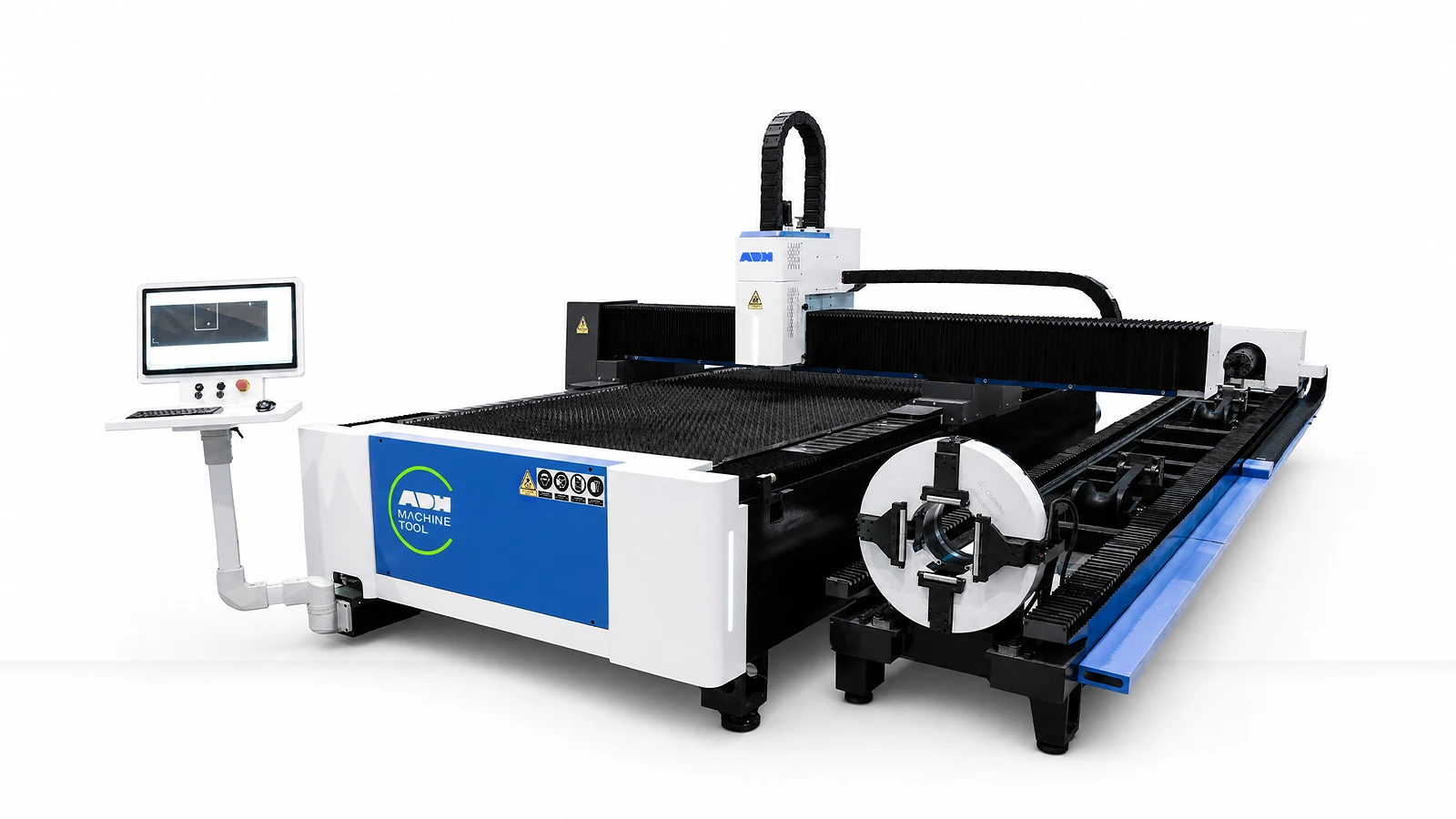
Sheet and Tube Cutting | ULFT Series
Bring sheet and tube cutting into one system, with the working format and handling options your production needs.
Technical specifications
ULFT combines an open sheet-cutting table with a tube station. Tube configurations offer a 220 or 350 mm chuck and nominal stock lengths of 6, 9 or 12 m. Select the sheet format and laser power separately, then match the chuck, supports and loading space to your tube sections.
| Series | Laser Power | Working Range | Chuck | Tube Length | Max Movement Speed | Max Acceleration | Positioning Accuracy | Repeatability | Working Voltage / Frequency (V, Hz) | Cooling Method | Source Scope |
|---|---|---|---|---|---|---|---|---|---|---|---|
| Unit | kW | m | mm | m | m/min | g | mm | mm | |||
| ULFT family | 1.5 - 60 | 3*1.5 /4*1.5 / 6*1.5 / 4*2 / 6*2 6 / 8 / 13 / 26*2.6 / 3.2 | Φ 220/350 | 6/9/12 | 140 | 1-1.5 | ≤ ± 0.03 | ≤ ± 0.02 | Three-phase AC380V, 50 Hz | Water cooling | Family-level source only; values do not define one model configuration. |
Dual-process inputs
A dual-use machine has one active cutting mode at a time; define both material paths before selecting the shared platform.
01
Provide format, material, thickness, load, gas and edge result.
02
Define profile, dimensions, wall, length, straightness, weight and remnant target.
03
Set sheet-to-tube ratio, product mix, nesting, mode changes, supports and handling.
04
Confirm chuck package, process software, loading, extraction, guarding and data interfaces.
Machine in operation
Watch the dual-use cutting sequence, then compare the shared platform, sheet path and tube path below.
Watch on YouTube (opens in a new tab)Product systems
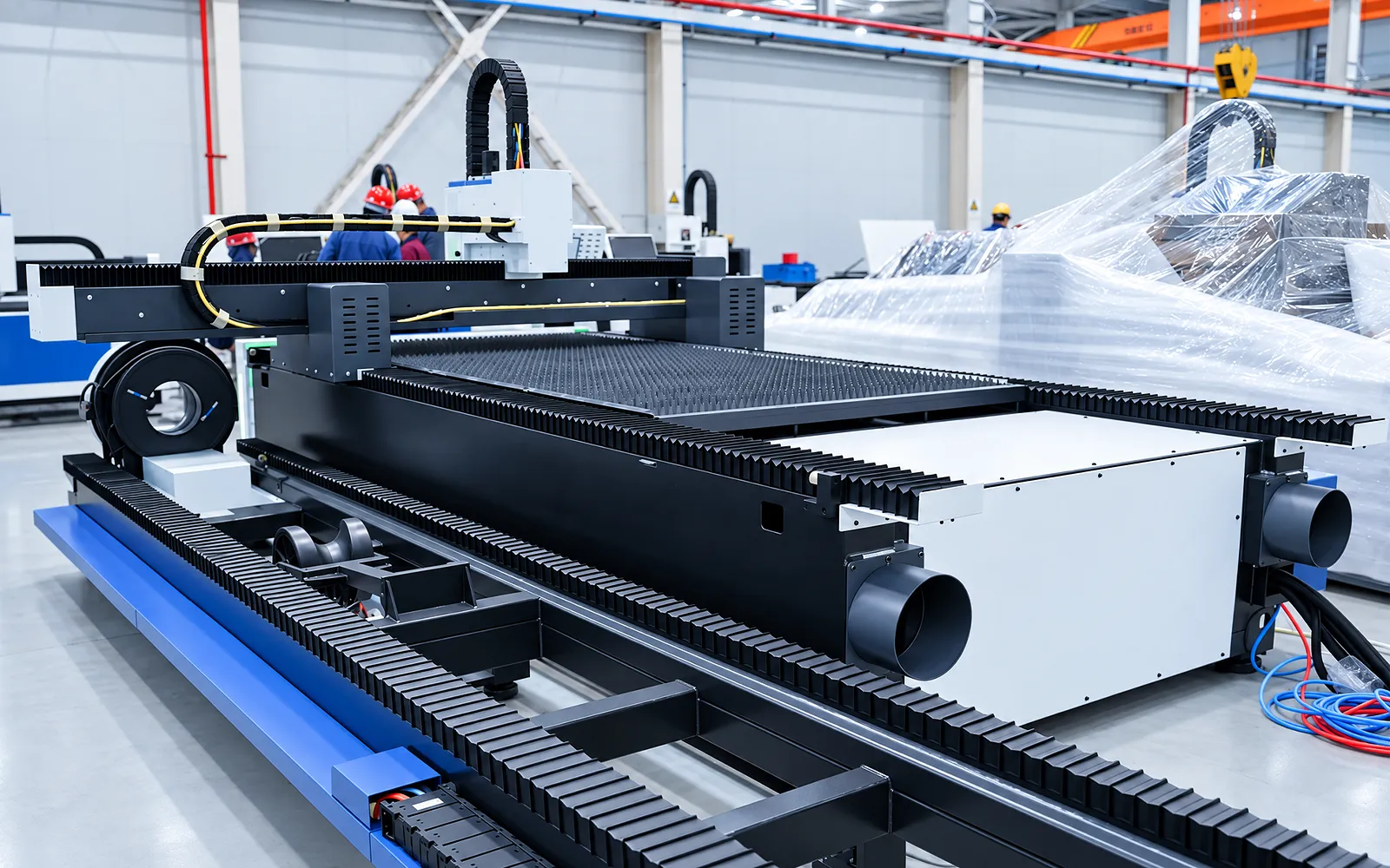
ULFT combines sheet and tube routes on a shared platform. The machine operates one cutting mode at a time, so changeover and the balance of sheet and tube jobs matter.
Shared platform
The sheet table and tube module share the cutting platform.
Use the engineering proposal to establish the exact configuration rather than relying only on the family summary.
Changeover
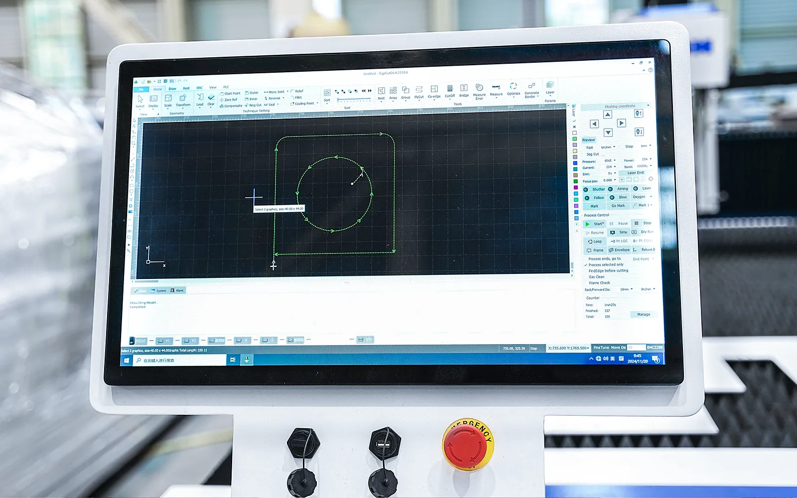
Changing mode changes the coordinates, supports and operating sequence.
Review how programs and stock are changed between sheet and tube jobs.
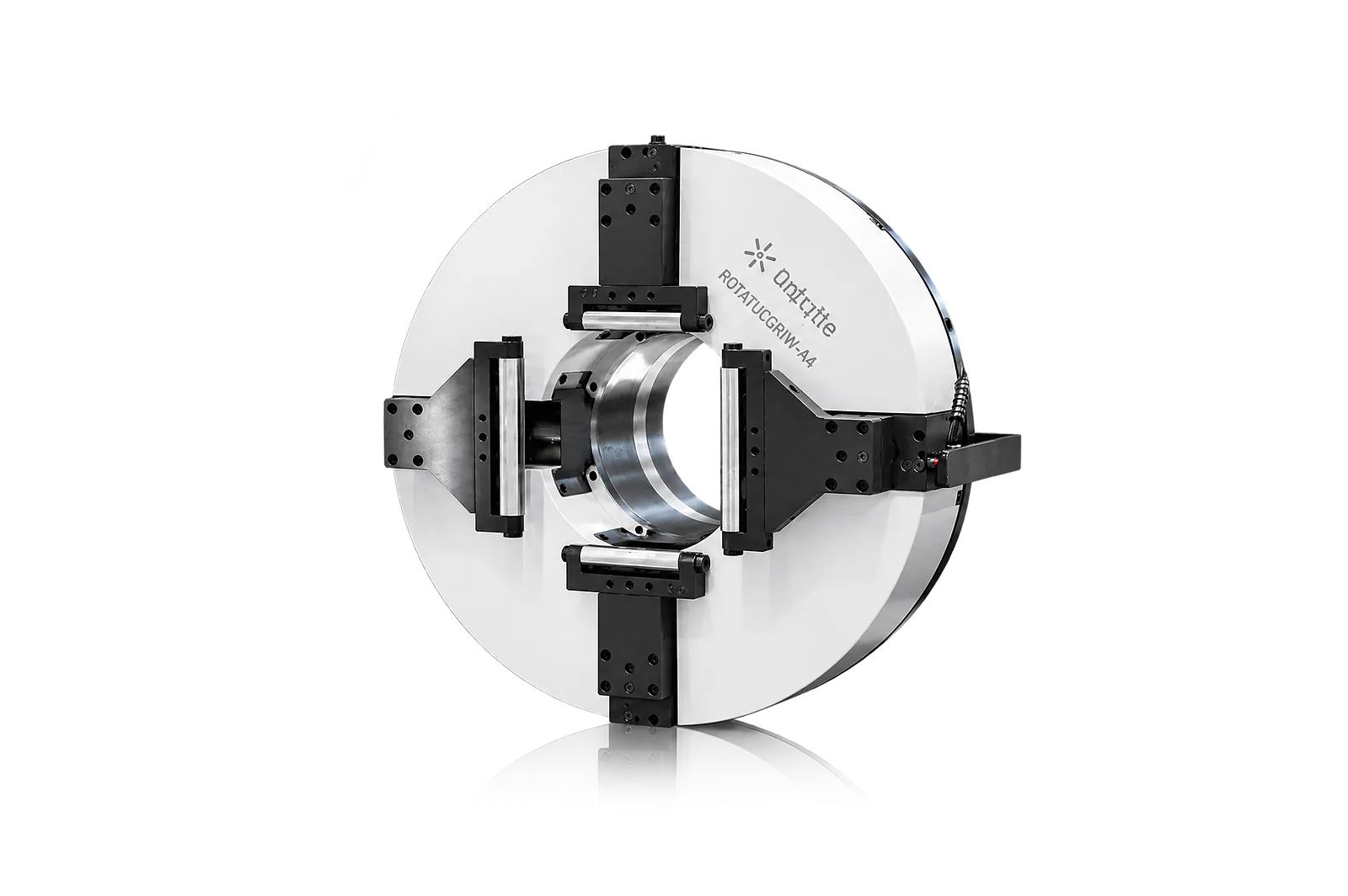
Tube gripping
The chuck grips and indexes the profile for the cutting sequence.
Select chuck geometry for the intended sections and review collision limits and usable tail length.
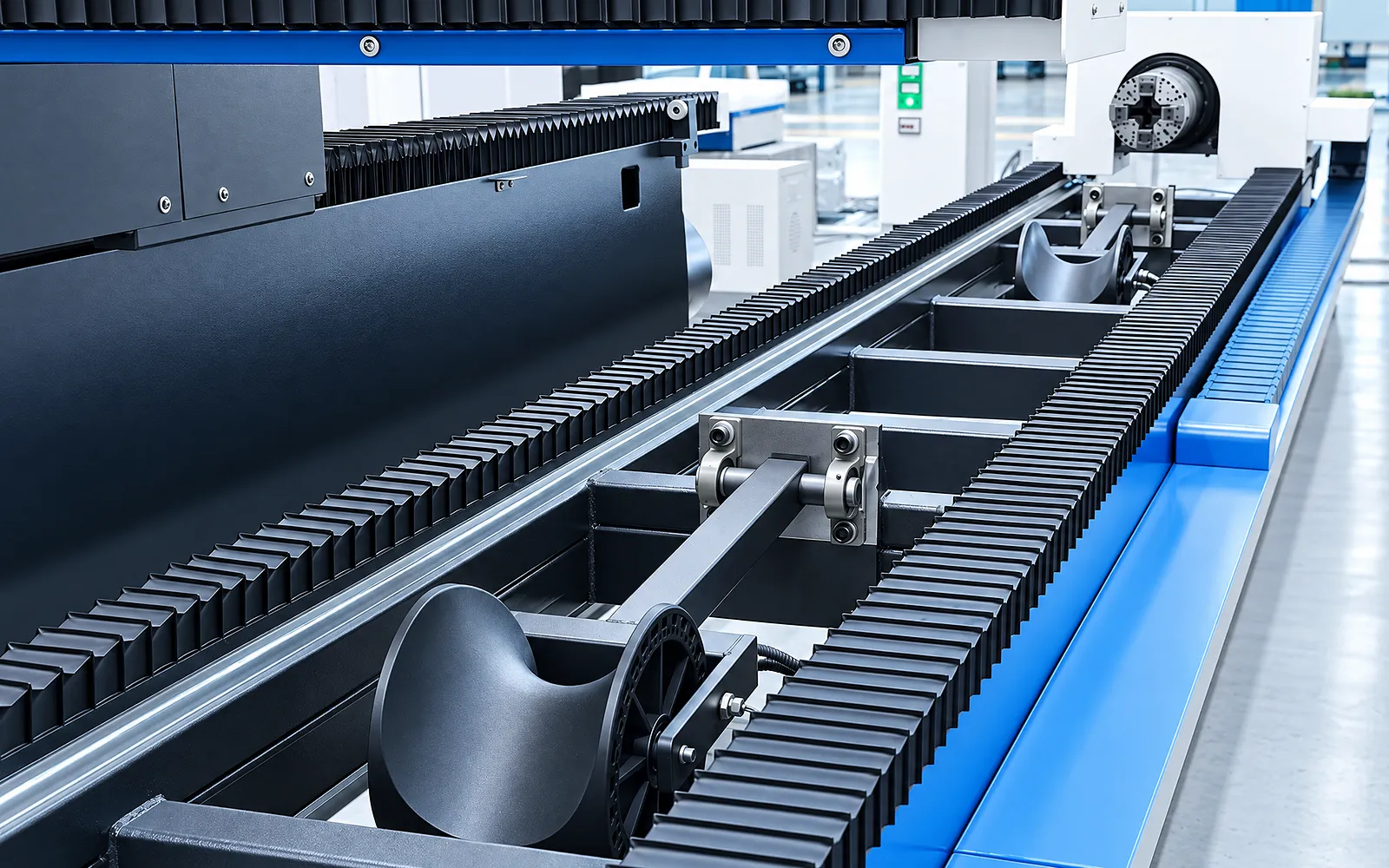
Tube support
Supports maintain the tube's presentation to the head as it rotates.
Match support to section shape, length and weight, including access and remnant removal.
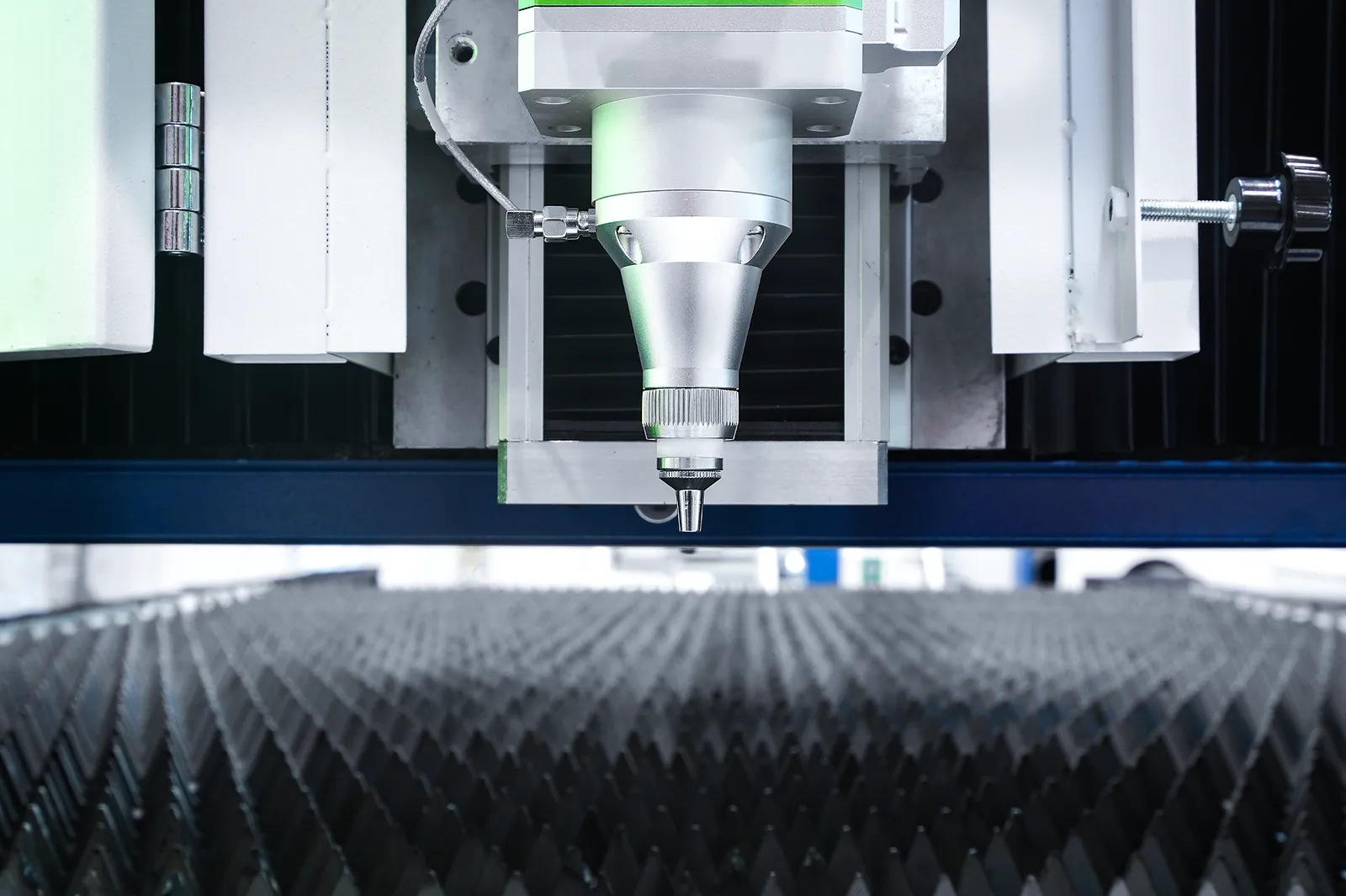
03
The shared source and head serve the active sheet or tube mode. Focus, gas, cooling and extraction must suit the material and process in that mode.
Review sheet and tube requirements separately when selecting power and head functions. Validate each intended material with an appropriate cut sample.
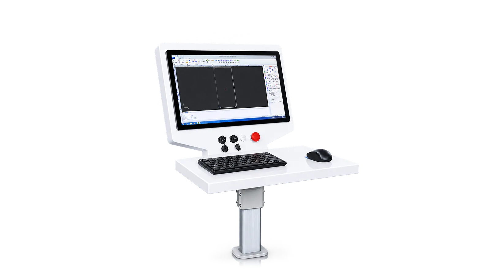
Programs
The control software coordinates the selected sheet or tube program.
Define the required program transfer. MES and remote functions are separate configuration choices.
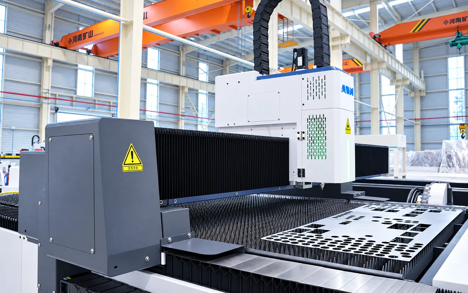
Handling interfaces
The handling plan defines how stock reaches the table or chuck and how parts leave.
Specify loaders, chuck-layout choices and the required equipment interfaces for the configured system.
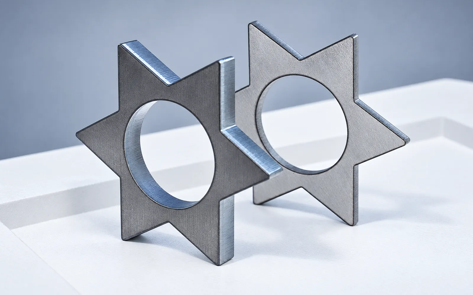
Sheet trial
Use a representative sheet part to test setup, programming, gas and cut quality.
Agree the sheet drawing and inspection criteria, including loading and part removal.
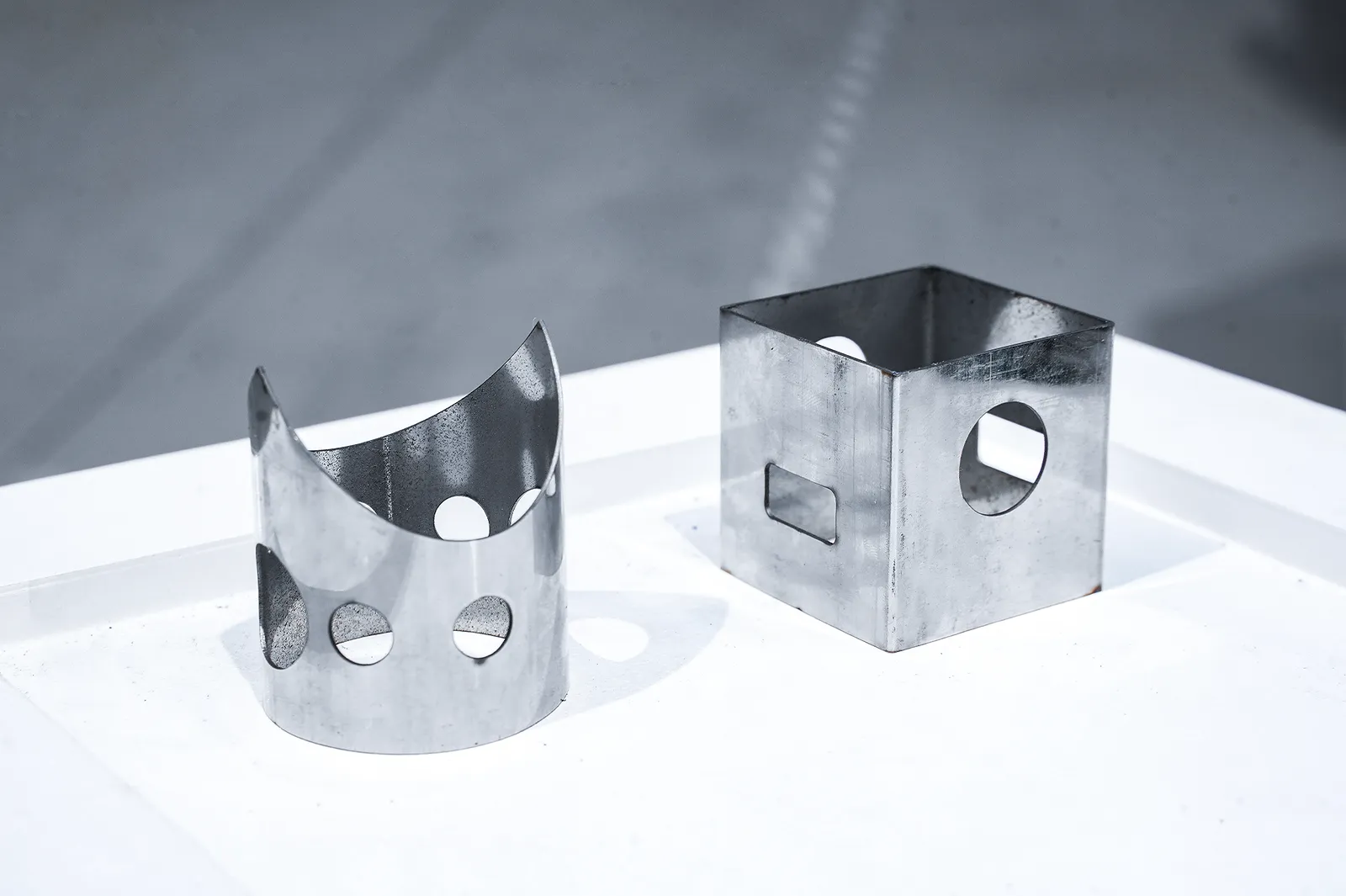
Tube trial
Use a representative tube profile to test the configured gripping, support and cutting route.
Agree separate inspection criteria for the tube job and include changeover and remnant handling.
Family selection
Confirm sheet format, tube capacity and handling for the selected ULFT configuration.
The ULFT system combines configured sheet format, power, chuck, tube length, motion, precision, voltage and cooling.
Sheet/tube loading, supports, enclosure, monitoring, extraction and data integration are conditional.
Confirm sheet and tube envelopes, chuck and support, process sample, remnant target, utilities and safety.
Related machines & selection
Through the machine lifecycle
Find the training, maintenance guidance and parts support your team needs. Services and availability are confirmed for your machine and location.
Before start-up
Prepare utilities, lifting and the installation area, then coordinate start-up and handover.
Review installation supportBefore production
Build the operator, programming and maintenance skills required for your delivered machine.
Explore trainingIn operation
Get support with the machine model, serial number and a clear description of the issue.
Request technical supportPlanned spares
Identify your machine and component so our team can check compatibility and availability.
Request service or partsSelf-service
Find video guidance for operating and maintaining your ADH machine. Check relevance to your model and configuration.
Browse support videosContract scope
Your quotation or contract defines included services, warranty, exclusions and responsibilities.
Review service scopeProject enquiry
Tell us what you want to make or improve. Technical details and drawings can follow.
Contact ADH
Name, email and a short description are enough to begin.